
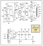
The rectifier sees CRC filter of 40u, 700R, 40u. The back bias supply circuit is incorrectly drawn for the -67V supply.
There is another drawing error: feedback cathode bias bypass capacitor is just across 4k7.
Perhaps follow the old original circuit, or a restoration/clone project.
There is another drawing error: feedback cathode bias bypass capacitor is just across 4k7.
Perhaps follow the old original circuit, or a restoration/clone project.
Thank-you. Yes the bias supply is fubar, cap should be shunt. I still don't understand how the power supply is CRC if the 700R resistor is below the cap to ground. Doesn't CRC refer to cap, series resistor, cap?
I've only been able to find 2 schematics, rather difficult to find (or afford) an original amplifier. I'm not sure if any of the clones would be correct, not that I know of any anyhow.
I've only been able to find 2 schematics, rather difficult to find (or afford) an original amplifier. I'm not sure if any of the clones would be correct, not that I know of any anyhow.
Follow the charging current pulses ")
Rectifier charges first 40uF up directly. Then that cap charges the +340V supply cap up via the 700R.
Back bias is a bit tricky to see sometimes - sometimes they use a choke instead of R. Sometimes the rectifier charges the first cap through an R, and the voltage across that R is then filtered for bias supply.
A choke between the first 2 PsU caps is always recommended, for a lot of reasons.
In this case, it replaces the 2K resistor. Voltage output will be a little higher, so you have to account for that in biasing etc. But do not keep both the choke and the resistor, we do not want a high impedance Power Supply.
In this case, it replaces the 2K resistor. Voltage output will be a little higher, so you have to account for that in biasing etc. But do not keep both the choke and the resistor, we do not want a high impedance Power Supply.

Here's the circuit redrawn easier to look at.
I built this amp but made some changes in the front end.
The low capacitance had some LF attenuation.
Also here is a youtube video of a Brook 12A circuit modified to run a quad of 300B triodes.
My friend David Beard made the video. YouTube
I built this amp but made some changes in the front end.
The low capacitance had some LF attenuation.
Also here is a youtube video of a Brook 12A circuit modified to run a quad of 300B triodes.
My friend David Beard made the video. YouTube
Attachments
Last edited:
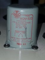
What did you use for the plate choke for the driver stage?
I used a UTC MQM-300 choke 300HY @ 3700 ohms. Got it off Ebay. Also I have the LT Spice for this. Send me your email I can forward you a copy. Assuming you have Spice on your computer?
I have not tried these but these grid chokes may be an option. http://bit.ly/2HdLsLD
Also I know for a fact that Heyboer has made the Brook 12-A choke clone before. They run around 3600 to 3700 ohms.
Attachments
- Status
- This old topic is closed. If you want to reopen this topic, contact a moderator using the "Report Post" button.
- Home
- Amplifiers
- Tubes / Valves
- Brook 12A Q