Hey, so I need to provide adjustable fixed bias for two power tubes from a 150-0-150V AC winding. Ultimately I need bias in the -130V to -150V range.. So anything that that works into is fine. I have some 10K pots that I want to use for the adjustment, as they're a no shaft type that work quite nicely for adjustment with a screwdriver.
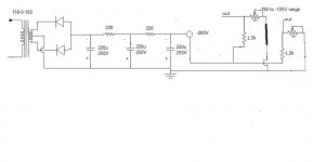
Here's a circuit I came up with for the bias supply which would provide -200V, and the adjustment section should allow me to provide between -190V and -125V

If this were just for a single tube I don't think it would be a big deal.. But I got thinking and the two sections at the end that provide the adjustment are in parallel.. So the values will be half..
Which actually might not be a huge deal.. I'm having trouble figuring out exactly what I'm going to end up with, with the paralleling of those sections.
Is there a better way I could do this so that the two adjustments are independent of eachother completely?
Here's a circuit I came up with for the bias supply which would provide -200V, and the adjustment section should allow me to provide between -190V and -125V
If this were just for a single tube I don't think it would be a big deal.. But I got thinking and the two sections at the end that provide the adjustment are in parallel.. So the values will be half..
Which actually might not be a huge deal.. I'm having trouble figuring out exactly what I'm going to end up with, with the paralleling of those sections.
Is there a better way I could do this so that the two adjustments are independent of eachother completely?
Last edited:
The fact that they are in parallel doesn't matter so long as they don't load the supply too much.
On my valve amp I just used one supply and fed that to the two grid resistors.
On my valve amp I just used one supply and fed that to the two grid resistors.
The fact that they are in parallel doesn't matter so long as they don't load the supply too much.
On my valve amp I just used one supply and fed that to the two grid resistors.
Right.. So with each bias adjustment circuit being 29K (1K + 10K + 18K), in parallel that load is 14.5K.. So with a 200V supply this parallel load is drawing (200V / 14.5K) 13.8mA. Which is fine for this particular winding.
I'm just having trouble actually calculating what my range is going to be with these parallel components.
The load is just the two bias supplies you have in parallel.
The grid resistors will be high values so can effectively be ignored.
The grid resistors will be high values so can effectively be ignored.
The load is just the two bias supplies you have in parallel.
The grid resistors will be high values so can effectively be ignored.
Yea, I don't have the grid resistors pictured in the above circuit. The wipers on the pots will feed the grid resistors.
I'm just not sure how to calculate the voltage divider outcome.. Is it just safe to assume that each independent resistance is halved.. So for the purposes of calculating voltages, that the 18K resistors are effectively 9K resistors, and my 10K pots are 5K pots, and the 1K resistors are 500 ohm?..
Last edited:
wow - brave reliance on the continuity of the wiper....
I'd be VERY inclined to design so the pot shunts the circuit to provide adjustment rather than rely on the pot maintaining 100% integrity at all times.
I'd be VERY inclined to design so the pot shunts the circuit to provide adjustment rather than rely on the pot maintaining 100% integrity at all times.
wow - brave reliance on the continuity of the wiper....
I'd be VERY inclined to design so the pot shunts the circuit to provide adjustment rather than rely on the pot maintaining 100% integrity at all times.
Hm.. Good thought.. Might just be difficult with 10K pots..
You have 200v for the dividers. it doesn't matter that more than one divider hangs off the 200v, they don't interact as you have drawn it. So no need to laboriously calculate parallel resistances. The parallel divider strings will add up to the current draw from the 200v, but not each other.
I also am concerned over depending upon the wiper for bias. I always design the adjust circuit with the pot wired as a variable resistor in the string. That way if the wiper lets go, we don't lose bias completely, it just reverts to the highest voltage.
I also am concerned over depending upon the wiper for bias. I always design the adjust circuit with the pot wired as a variable resistor in the string. That way if the wiper lets go, we don't lose bias completely, it just reverts to the highest voltage.
FWIW, i use fixed bias only when i am not selling the amp....
amps that go to other owners are converted to cathode resistor bias....
so then the new owner need not worry about bias loss issues...
amps that go to other owners are converted to cathode resistor bias....
so then the new owner need not worry about bias loss issues...
I suggest that you change the bias supply like the drawing attached. (sorry for the quality of the drawing).
If (when) the wiper fails, the tubes will have higher negative voltage, and conduct less, wich means "no harm done" exept the pot.
If the wiper fails in your drawing, the tube will loose the negative bias and the plate current will rise to a level that could destroy the tube.
I would also suggest that you use some other values for the resistor/pot, say 2.7k resistor and 20k pot. This only to draw less current from the bias supply.
Attachments
In your circuit the 1.5k resistors serve no purpose. Also, you have a lot of smoothing stages. You really only need a reservoir cap, and a single cap after the pot wiper, to get more than enough smoothing. Another trick is to add a diode so the bias supply stays charged for longer after switch off. This can cure problems with current surges if the power is switched off and quickly on again. R2 is a pull-up resistor to protect against the wiper not making contact. R3 is a (slow) discharge resistor.

Last edited:
Yes, add Merlin's R2 as a fallback resistor even if you don't do the other things he suggests. Anything from a few hundred K up to 1M will do. A resistor costs a lot less than a new set of output valves!
I'll toss my hat in the ring and advocate for R2, it's really all that's needed, and it can be an order of magnitude greater (or more) than the actual pot resistance as long as the maximum allowable grid circuit resistance is not exceeded. (If the pot wiper opens)
As an aside some pots are much more reliable than others, and for bias adjustment pots I use mil spec RV4LAYSA pots made by PEC or Ohmite.
RV4LAYSA103A Precision Electronics Corporation | Potentiometers, Variable Resistors | DigiKey
I admit to omitting R2 in a lot of instances with these pots particularly long ago and after 28yrs I am still waiting for my first failure. I do, however, recommend that resistor.. 😀
In your circuit the 1.5k resistors serve no purpose. Also, you have a lot of smoothing stages. You really only need a reservoir cap, and a single cap after the pot wiper, to get more than enough smoothing. Another trick is to add a diode so the bias supply stays charged for longer after switch off. This can cure problems with current surges if the power is switched off and quickly on again. R2 is a pull-up resistor to protect against the wiper not making contact. R3 is a (slow) discharge resistor.
Okay.. So this circuit was a little harder for me to understand..
But I drew it up here:

I think I'm understanding this correctly, in that when the wiper on the 10K pot is set to 0 making the divider like 0 on the top, and 20K on the bottom, then I have -200V output.. When the wiper is set to 10K, then I have 10K on the top and 10K on the bottom which makes the output -100V.. Is that right?
I also reduced one leg of filtering. I'm not sure what values to put for the components with question marks.
See DF96 and my post on the question of R2, determine its value based on the combination of all grid circuit resistances such that the total is just less than the maximum allowed for fixed bias operation for the output tube used.
R3 could be quite large as a long discharge time constant is not going to hurt anything. (Even something like 1M ohm would be ok here.)
C2 should be chosen such that the overall time constant for the bias supply allows it to rise to full bias before the plate voltage is applied and/or filaments are warm. The important thing is that plate current not exceed safe values during warm up, preferably rising smoothly to the set value.
I suggest 100k for both.I'm not sure what values to put for the components with question marks.
See DF96 and my post on the question of R2, determine its value based on the combination of all grid circuit resistances such that the total is just less than the maximum allowed for fixed bias operation for the output tube used.
R3 could be quite large as a long discharge time constant is not going to hurt anything. (Even something like 1M ohm would be ok here.)
C2 should be chosen such that the overall time constant for the bias supply allows it to rise to full bias before the plate voltage is applied and/or filaments are warm. The important thing is that plate current not exceed safe values during warm up, preferably rising smoothly to the set value.
Thanks. The bias circuit is feeding the gate of a mosfet source follower, and that gate resistance can be quite high.
How does this look? Do you guys think the 10K pot and 10K R1 value are suitable?

I had originally figured on using the bias circuit that Tubelab did on his powerdrive design.. I guess it's fine operationally to use it like he did, but not necessarily the best option long term..

Last edited:
Provided that the negative supply is enough to bias the valve to cutoff (or nearly) then R2 etc. can be a bit bigger than the datasheet max as thermal runaway is unlikely. Most people continue to use infinity here, so anything smaller has benefit!kevinkr said:See DF96 and my post on the question of R2, determine its value based on the combination of all grid circuit resistances such that the total is just less than the maximum allowed for fixed bias operation for the output tube used.
- Status
- Not open for further replies.
- Home
- Amplifiers
- Tubes / Valves
- Bias circuit for fixed bias