yes, got it, thanks.
after all from the viewpoint of the valve the bridge is not different from ct with respect to current flow.
i never used center tapped rectifiers tbh, since i make my own traffos....
besides transformer utilization is better without the center tap.
astouffer,
and . .
tonimxp,
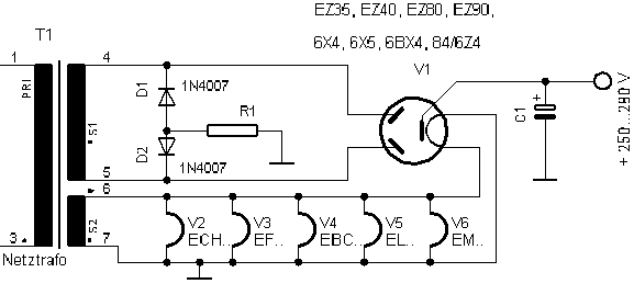
The resistor, R1, is there to limit the peak cathode current of the 6X4 cathode. The peak current happens each and every alternation of the high voltage secondary (positive alternations, and negative alternations). 2 alternations per power mains cycle, 50Hz = 100 alternations, 60Hz = 120 alternations.
The amount of the total series resistance that a 6X4 requires is dependent on 4 things:
Note: DCR = DC Resistance of transformer winding(s)
1. The DCR of the power transformer primary DCRpri.
Multiply DCRpri X (the step-up turns ratio of the primary to the secondary).
Example: Primary is 120V, secondary is 360V, so the step up ratio is 3 X.
Suppose the primary DCR is 10 Ohms.
The effective DCR of the primary is 10 X 3 = 30 Ohms (30 Ohms is reflected "in series" with the DCR of the secondary).
2. The DCR of the power transformer secondary, DCRsec.
Suppose that is 100 Ohms.
3. The resistance of R1.
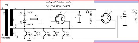
4. The number of uF of the first filter capacitor(s), C1 and C2 on the schematic,
The higher the number of uF, the more likely a resistance, R1 is needed).
The required total series resistance, is according to applied voltage, and uF of the first cap; should be in the detailed 6X4 data sheets.
DCRpri x step up ratio; DCRsec, and Rl resistance according to:
A. The secondary voltage,
and
B. The number of uF of C1 (C2 for the other tube).
Suppose R1 is set to 50 Ohms.
We have 30 + 100 + 50 Ohms total resistance (180 Ohms) to limit the peak cathode current into the input filter cap, C1.
If the data sheet called for 150 Ohms with the uF of C1, we are good.
and . .
tonimxp,
The resistor, R1, is there to limit the peak cathode current of the 6X4 cathode. The peak current happens each and every alternation of the high voltage secondary (positive alternations, and negative alternations). 2 alternations per power mains cycle, 50Hz = 100 alternations, 60Hz = 120 alternations.
The amount of the total series resistance that a 6X4 requires is dependent on 4 things:
Note: DCR = DC Resistance of transformer winding(s)
1. The DCR of the power transformer primary DCRpri.
Multiply DCRpri X (the step-up turns ratio of the primary to the secondary).
Example: Primary is 120V, secondary is 360V, so the step up ratio is 3 X.
Suppose the primary DCR is 10 Ohms.
The effective DCR of the primary is 10 X 3 = 30 Ohms (30 Ohms is reflected "in series" with the DCR of the secondary).
2. The DCR of the power transformer secondary, DCRsec.
Suppose that is 100 Ohms.
3. The resistance of R1.
4. The number of uF of the first filter capacitor(s), C1 and C2 on the schematic,
The higher the number of uF, the more likely a resistance, R1 is needed).
The required total series resistance, is according to applied voltage, and uF of the first cap; should be in the detailed 6X4 data sheets.
DCRpri x step up ratio; DCRsec, and Rl resistance according to:
A. The secondary voltage,
and
B. The number of uF of C1 (C2 for the other tube).
Suppose R1 is set to 50 Ohms.
We have 30 + 100 + 50 Ohms total resistance (180 Ohms) to limit the peak cathode current into the input filter cap, C1.
If the data sheet called for 150 Ohms with the uF of C1, we are good.
Last edited:
tonimxp,
Here is a complete 6X4 data sheet:
https://frank.pocnet.net/sheets/049/6/6X4.pdf
I hope that will help you better understand what I wrote in my Post # 11.
I was surprised by the graph that shows some operating conditions with over 500 Ohms of total series resistance.
Here is a complete 6X4 data sheet:
https://frank.pocnet.net/sheets/049/6/6X4.pdf
I hope that will help you better understand what I wrote in my Post # 11.
I was surprised by the graph that shows some operating conditions with over 500 Ohms of total series resistance.
There is a similar thread here ...
tube-rectifier-transformer-center-tap
I don't think the resistor is necessary. Aren't the diodes just creating a virtual centre tap? There is a schematic in that thread, and some suggestions to bypass the diodes with a snubber, to minimise noise.
Edit: Missed some posts. The resistor is required if the DCR of the PT is less than the minimum required for the rectifier.
Aren't the diodes just creating a virtual centre tap?
Well, they handle the negative half wave currents whereas the tube does the positive.
I wouldn't call that "virtual" because a VCT is more or less a voltage reference point but does not carry load current.
- Home
- Amplifiers
- Tubes / Valves
- 6X4 Tube Rectifier Bridge