Hi,
I've been reading about how a diode between screen and plate in lieu of the usual resistor for triode connection has some advantages, but I cant seem to find any explanation as to why this might be.
Can anyone share some insight with regard to this?.
Thank you,
LH/S
I've been reading about how a diode between screen and plate in lieu of the usual resistor for triode connection has some advantages, but I cant seem to find any explanation as to why this might be.
Can anyone share some insight with regard to this?.
Thank you,
LH/S
I use D3A extensively in various projects and have found a 100 ohm to 1K resistor between the screen grid and plate to be fine. There is some feeling that larger values out to 3.32K or so may further improve linearity; I've not verified that supposition as I find linearity to be way more than adequate without any special tweaks which undoubtedly hold true for just that given sample.
I strongly recommend the resistor as the D3A makes a darned fine VHF oscillator without it in some instances. Install it quite close to the pin!
I strongly recommend the resistor as the D3A makes a darned fine VHF oscillator without it in some instances. Install it quite close to the pin!
Member
Joined 2009
Paid Member
I'm wondering if you are thinking of protection against thermal runaway if the screen grid gets too hot and starts emitting electrons instead of collecting them?
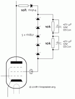
Anyhow, this link shows lots of diodes to keep you busy 🙂
Pentodes & Tedrodes to Triodes
Anyhow, this link shows lots of diodes to keep you busy 🙂
Pentodes & Tedrodes to Triodes
Attachments
I've lost the page I was on, and cant seem to find it.
It had some mentioning about (and this is vague) the diode blocking AC signal transferred to G2 to plate (and therefore output).. dunno - when I get time I'll try finding it again, it was well written and convincing to my mind.
As an aside the KandKaudio guy says about the same WRT diode connection (and yeah, I want the CC resistor to help tame the oscillations - its a given) he cites a clear improvement (and he's not a knock about type of guy - has some good credentials/history with design = implementation) but states that he's not come across anyone who can explain = why.
I need more time, I'll find it eventually and post back, alternatively, I just add the diode 🙂
Life is good once you get over it.
LH/S
Yes, this is an example of the 'creative' ideas to be found on that page. Complete nonsense, of course; to pass DC and block AC you need a choke not a diode.Ludwig Haus said:It had some mentioning about (and this is vague) the diode blocking AC signal transferred to G2 to plate (and therefore output).
The main effect of adding a diode in the g2 circuit is to reduce the g2 voltage by about 0.6V. This will of course have a huge effect on audio quality; even the wife in the kitchen will comment on the smoother highs and night and day improvement in soundstage.
if by kandkaudio, you mean Kevin Carter (aka KevinC), you can send him a PM.
If only.
He says that he doesn't know why..
LH/S
Yes, this is an example of the 'creative' ideas to be found on that page. Complete nonsense, of course; to pass DC and block AC you need a choke not a diode.
The main effect of adding a diode in the g2 circuit is to reduce the g2 voltage by about 0.6V. This will of course have a huge effect on audio quality; even the wife in the kitchen will comment on the smoother highs and night and day improvement in soundstage.
My diodes drop 0.7V - maybe I got the wrong ones? 😛
Tell me, what happens when you pass AC through a diode? - we all know the answer, rhetoric beats sarcasm each and every day, but still, would one reliably expect a difference.. and thereto. But, and again, the KandKguy isn't a Johnny come lately. (if he came at all - yeah, don't follow that line of thought to closely = you might end up needing a tissue or three, all dependant on your persuasion - hey I'm not here to judge, just to share some love) 🙂
Did I tell you yet that I'm amazing?
I take my inspiration from Iggy Pop - but just only as of late, and in retrospect it was worth coming in for the big win - and to think you made it so easy.
LH/S
Last edited:
K&K Thread
It boils down to this:
"The diode's high reverse impedance prevents current from flowing from Screen to Plate."
If the plate and the screen are tied together, there is zero potential between the two, thus no current flows... Or perhaps there is "electron stream" flowing about that is blocked by the magic diode.
Last edited:
It all depends on how much DC you are passing at the same time.Ludwif Haus said:Tell me, what happens when you pass AC through a diode?
If the diode is reverse biased for part of the AC cycle then the result will be significant asymmetric distortion. However, some people can't hear serious peak clipping, so this slightly smaller effect may pass them by or even be thought 'musical'.
To a first approximation, a forward biased diode acts as a constant voltage drop.
To a first approximation, a reverse biased diode acts an an open circuit.
To a first approximation, a diode switching between these two states is very nonlinear so you don't want it anywhere near your audio signal.
The magic diode,
I use it..😀
In triode on output tubes its a bit clean maybe even sterile sounding<<sounds nuts I know.
In U/L +diode<<prefer it to U/L.
Pentode it can be used but pentode is just as good.
In signal triodes yes I run it.
The only thing I can say is there will always be a .7V drop on the grid.
The effect is more pronounced on Op tubes<<I think its the back EMF but that's just an opinion.
I have heard all sorts of rhetoric about diodes and tubes one being the reverse diode across the OP tubes suppressing the electron cloud but take it with a pinch of salt!
I'm not saying its wrong just that I have never seen any proof.
However I think the magic diode sounds different<<the change is like a reduction in the warm tube sound..(the woolly mush you can get that people link to the so called "Tube sound")
So its another sound like triode, pentode, U/L and Electron stream in one amp I have all these settings on a switch and it stays in U/L +the magic diode..which is strange because I could choose any one of the others..NB I have RH shade F/B as an option as well but the magic diode in U/L is the favourite.
NB I tried Ultra Fast and they didn't sound as good..don't ask its an opinion.
Regards
M. Gregg
Last edited:
Many years ago,
I tried different types of diode across power tubes in a PP amp. The Ultra fast sounded very bright and diodes like BYV96E sounded more warm and natural.
NB again the diodes sounded better in than out of circuit.
All the above is just an opinion..but the magic diode has a similar signature.
In the electron stream blog it suggests using capacitors across the diodes however I have never tried it.
Also the diode is not supposed to replace any resistance in the grid connection and is in series with it..
The problem with inverse parallel diodes on power tubes is if the diodes go short it can damage the output transformer. (fusing is advised)
The Electron stream magic diode is different and creates a similar sound without the danger should it go short or open circuit.
Regards
M. Gregg
Last edited:
Here is another opinion,
I have heard changes in sound with small RF chokes fitted in grid connections.
Just for interest.
Years ago I had some fun using diodes and various ideas cap rolling altering F/B with no measurements just by ear for a laugh.
I used a pioneer A300X as a comparison at the start and at the end I could not tell the amps apart with no comparison after the first comparison where the tube amp sounded warm and mushy..it was a shock because I expected the tube amp sounded better than the pioneer but it was so close it was mad..the tube amp was louder just because it was a more powerful circuit 8X El34 PPP..
Regards
M. Gregg
Last edited:
- Status
- Not open for further replies.
- Home
- Amplifiers
- Tubes / Valves
- D3a - diode between screen & plate (triode) ?