it's pretty accurate as long as you enter all the parameters correctly (such as adding a series resistance Rs
that matches the rp of the input stage).
It's the output impedance of the first stage that is needed for this, not just the Rp.
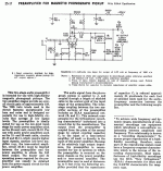
It may help to refer back to the RCA original (uploaded) and what the tweaks do. The RCA original has so/so bass extension and absolutely wretched drive capability.
Grid leak biasing the 2nd gain block lightly loads the EQ network, which improves bass performance. Thank you Thorsten Lösch. The DC coupled ZVN0545A source follower greatly improves the preamp's drive capability. The little FET is extremely easy to integrate and is very transparent. Experience has shown that a protective 12 V. Zener diode should be installed between the source and gate circuitry of the MOSFET. Power on and "steady state" conditions do differ.
The use of 20 Mohm grid to ground resistor impacts on the RIAA network and adjustment of some parts values is necessary. Perhaps the "best" way to deal with the interstage coupling cap. is to acquire several Soviet surplus K40 0.22 μF. parts and cull out a pair that measure on the low side.
BTW, the change from 22 K to 24 K is well known and should be part of an "original" build. Circa 1950, 22 K was what could be sourced, at reasonable cost.
Attachments
It's the output impedance of the first stage that is needed for this, not just the Rp.
You're correct, I wasn't clear there.
One needs to figure out what the output impedance of the first stage is, and enter that as Rseries in the program.
Output impedance is usually calculated as the plate load resistor value in parallel with the internal plate resistance of the tube, at the chosen operating point.
--
Can someone explain the size relationship between R6 (255K-266K) and the capacitor (.166uf-.18uf)?
Grossly simplifying R6 + rp//100K in conjunction with R1 and C4 set the low frequency pole and zero for the RIAA, C1 takes care of the other pole. Look up the Lipshitz RIAA EQ paper from University of Waterloo, Ontario or the Audio Amateur article which was a bit more targeted for details. The coupling cap has a huge impact on the EQ accuracy at the low end of the response range and too small results in a lot of roll off and non-conformance with the RIAA response curves. I tend to go fairly big here. (rumble and warp are not a big problem in my system).
Getting these values right is critical to getting good conformance with RIAA and it is not unreasonable to measure and trim if you have the means to do so. If C1, C4 and R1 are trimmed to within 1% or better of the theoretical ideal generally all you have to do to bring things in line is to trim the value of R6 to compensate for rp of the input stage, usually this will not need to be done again with a tube change. (I have achieved +/- 0.1dB RIAA conformance in some of my tube phono pre projects with careful trimming and measuring.)
The RIAA caps. are isolated from B+ by the interstage coupling cap. and low WVDC parts are fine. OTOH, the interstage coupling cap. does "see" B+. Take no prisoners and use a 400 WVDC rated part.
- Status
- Not open for further replies.
- Home
- Amplifiers
- Tubes / Valves
- Radiotron/Eli Duttman phono change C1 to .00391?
