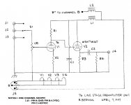
I just finished my version of the 76/6SN7GT preamplifier, closely following the Berman schematics as published in Sound Practices #13 of 1997.
The power supply chassis uses a 5R4-GY rectifier followed by a L-C-L-C filter,
L's are 10H and C's are 20µF paper in oil.
A 22k bleeder resistor is connected across the supply.
I did some measurements purely on this power supply, without the preamp chassis connected.
The high voltage is about 440V, the ripple is 50mV, 100Hz.
Am I right to think this is simply not good enough?
Furthermore, the high voltage shifts up and down in a 200mV band at a frequency of roughly 4 Hz. This I cannot explain, maybe it is simply the mains fluctuation, but why is it not filtered away?
When connecting the preamp chassis, a faint hum is audible in a silent room.
Also, now and then a plopping noise is heard, still present when referencing the filament supply to the high voltage supply.
When displaying on an oscilloscope the high voltage supply together with the output of the preamp with zero volume, I see the output follows the 4 Hz modulation of the high voltage supply (described above).
Any suggestions how to correct these items are very welcome!
Greetings, 968driver.
10H and 20uF will filter out frequency components above about 11Hz. 4Hz will not be attenuated very much. 100Hz will be attenuated by two such LC cells by about 1/81 or -38dB. I guess you are drawing much less than the required critical current to get proper choke input PSU action?
To stop the PSU putting out the 4Hz you either need a cleaner mains supply or much bigger PSU caps. To stop the 4Hz from passing through the preamp you need much smaller coupling caps.
Hum can come from supply rail ripple or poor grounding. The most important thing is to ensure that the mains transformer secondary centre tap does not connect directly to the chassis but to the negative terminal on the first cap. Then to the second cap. Then to the audio circuit. From somewhere in there to chassis.
I am puzzled by the 200mV 4 Hz noise on the high voltage supply. Where does it come from?
The preamp is DC coupled, only one capacitor (1µF) at the cathode follower output.
As a brute force measure, I tried a 910 µF capacitor on the high voltage.
This reduced ripple to about 1 mV, and the 4 Hz noise became almost invisible.
But I don't like this solution and will not use it.
It seems odd to me that this highly acclaimed design has a lot to be desired...
Yes, I have raised the heater supply, the heater-cathode voltage difference is about 80V, but this did not change anything about the frequent plopping noises.How's your heater situation?
Have you raised it with DC potential of maybe 40V or so?
I would like to avoid a seperate heater supply for the 6SN7GT if possible.
Attachments
There's a number of things that could be causing that 4Hz. It could come from the AC line; it could be a resonance in the secondary circuit of the PT; it could be a resonance between the chokes and the caps; it could even be from the audio circuit if parts of it are directly coupled (the second stage in the DC system is finding it's op point).
The 4Hz is most probably not causing the hum; the heater circuit is the first place I'd look. So, what's the heater DC situation?
The 4Hz is most probably not causing the hum; the heater circuit is the first place I'd look. So, what's the heater DC situation?
Heater supply is DC, C-R-C filter, 33000 µF - 0,47 Ohm - 33000 µF.Ok, good. The heater DC supply is properly capacitor bypassed to ground?
Heater supply is referenced to high voltage resistive divider 120k - 47k, decoupled by 100µF capacitor.
Agreed, the 4 Hz has nothing to do with the faint hum of the preamp.There's a number of things that could be causing that 4Hz. It could come from the AC line; it could be a resonance in the secondary circuit of the PT; it could be a resonance between the chokes and the caps; it could even be from the audio circuit if parts of it are directly coupled (the second stage in the DC system is finding it's op point).
The 4Hz is most probably not causing the hum; the heater circuit is the first place I'd look. So, what's the heater DC situation?
It also has nothing to do with the preamp, since it is present in the power supply itself, without the preamp connected.
On the scope, it is a more or less sinusoidal/sawtooth 4 Hz waveform, on top of the 440 V high tension. This 4Hz waveform is itself modulated by the 50 mV ripple.
Berman 76 preamplifier, problems solved!
I first built this preamplifier closely following the schematics as published in Sound Practices number 13 of 1997.
Problems were: some annoying 100 Hz hum and frequently a popping noise .
.
My solutions:
1. in the original L-C-L-C filter the C's are 20 µF. I put in parallel of each 20 µF capacitor a 330 µF elco. No more hum and no more pop noises.
2. I added a seperate heater supply for the 6SN7 tubes, referenced at 75 V by a voltage divider from the high tension supply.
The heater supply for the 76's is referenced at ground potential.
With these modifications, I am fully enjoying this design!
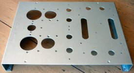
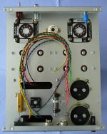
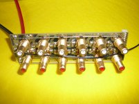
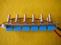
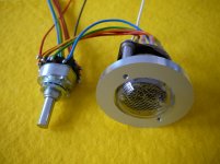
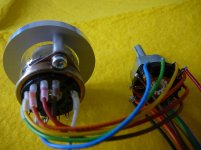
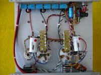
Added are some pictures of the construction and the nixie tube source indicator.
Best regards, 968driver.
I first built this preamplifier closely following the schematics as published in Sound Practices number 13 of 1997.
Problems were: some annoying 100 Hz hum and frequently a popping noise
.My solutions:
1. in the original L-C-L-C filter the C's are 20 µF. I put in parallel of each 20 µF capacitor a 330 µF elco. No more hum and no more pop noises
.2. I added a seperate heater supply for the 6SN7 tubes, referenced at 75 V by a voltage divider from the high tension supply.
The heater supply for the 76's is referenced at ground potential.
With these modifications, I am fully enjoying this design
!Added are some pictures of the construction and the nixie tube source indicator.
Best regards, 968driver.
Attachments
Thanks!
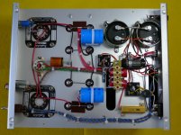
I have put some pictures of the finished power supply and preamplifier here:
http://www.diyaudio.com/forums/tubes-valves/71300-photo-gallery-684.html
The Rafaelite chokes on the power supply are 100% O.K., nicely made, not getting warm and no noise at all.
Best regards, 968driver.
I have put some pictures of the finished power supply and preamplifier here:
http://www.diyaudio.com/forums/tubes-valves/71300-photo-gallery-684.html
The Rafaelite chokes on the power supply are 100% O.K., nicely made, not getting warm and no noise at all.
Best regards, 968driver.
- Status
- This old topic is closed. If you want to reopen this topic, contact a moderator using the "Report Post" button.
- Home
- Amplifiers
- Tubes / Valves
- Berman 76 preamplifier, I need some advice please