I have some mini Russian tubes that I want to test quickly. I don't have a way to supply "high voltage" AC signal so I'm using 3 DC power supplies and plan to take a bunch of points and chart them using Excel.
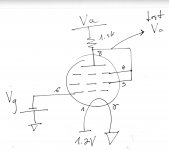
The tubes are 1zh24b. I'm wiring them as shown below (no idea if this is correct). The numbers near the tube elements (components?) are the pin numbers.
Connections:
1 DC power supply with 1.2V connected to pin #1, #2 goes to GND. This is the heater.
The suppressor grid & screen grid are shorted to the anode. That junction is connected to another DC power supply through a small resistor. The voltage at the anode is monitored using a DVM. The power line has an amp meter is series which monitors the anode current.
The control grid is hooked up to the 3rd DC power supply which applies various negative voltages.
As for the measurement procedure - The grid voltage is set to a known value (for example 0V) and the anode voltage is stepped from 10V to 30V. At each step, the anode current is being read.
That's it. So how bad is this setup? Will this blow up my tube?")
The tubes are 1zh24b. I'm wiring them as shown below (no idea if this is correct). The numbers near the tube elements (components?) are the pin numbers.
Connections:
1 DC power supply with 1.2V connected to pin #1, #2 goes to GND. This is the heater.
The suppressor grid & screen grid are shorted to the anode. That junction is connected to another DC power supply through a small resistor. The voltage at the anode is monitored using a DVM. The power line has an amp meter is series which monitors the anode current.
The control grid is hooked up to the 3rd DC power supply which applies various negative voltages.
As for the measurement procedure - The grid voltage is set to a known value (for example 0V) and the anode voltage is stepped from 10V to 30V. At each step, the anode current is being read.
That's it. So how bad is this setup? Will this blow up my tube?
Attachments
Hi. I'm waiting for a bunch of these mini rod pentodes in the post and I plan on testing in a similar way.
You can try a bunch of different ways with this tube like running the supp grid to ground, or connecting grid 2 to anode through a resistor creating nfb. I've seen one schema using grid 2 as input with g1 and supp going to the anode.
I'd love to see your chart as these are pretty interesting tubes. I plan on trying as many quick and dirty circuits as I can think of and if I blow a few of these $1 tubes that's ok. Feeding the anode through a variable constant current source should decrease that risk.
TM
Check out this thread... http://www.diyaudio.com/forums/tubes-valves/203435-1sh24b-pre-amp-buffer.html
TM
TM
There is some really good reading starting about halfway to the bottom of this page with regards to this tube.
Russian Subminiature Tubes
Russian Subminiature Tubes
Space-cake,
Your #1 post schematic is how I operate the tube in a linestage application. Pin 3 is a screen, in my applications I found no difference between leaving it unconnected or grounding it to signal ground.
Matt
So how did it work out with this tube?
TM
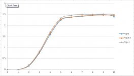
So I ran a few quick tests and the outcome is attached.
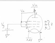
The setup is like so:
Pin #1 connected to 1.2V
Pin #2 & 3 to GND (cathode / heater & screen)
g1 & g3 & anode to Va (pins 6, 4 & 8)
Pin #5 connected to control voltage
The lines are very straight, however I have a feeling that my control voltage should be much lower for a low anode supply like I am using. In fact, after reaching Va over 10V I can see the mA meter falling slowly to lower and lower currents.
X axis is anode voltage, Y axis is anode current in mA.
Attachments
- Status
- This old topic is closed. If you want to reopen this topic, contact a moderator using the "Report Post" button.
- Home
- Amplifiers
- Tubes / Valves
- Mini Pentode tube testing in Triode mode?