This is an old question, I know, but I'm raising it from the dead because I'm having a very similar problem with hum in the midrange of the volume pots for the right channel (amped by tube V2), on the circuit in the SAMS attachment (an old record player tube amp I'm working on restoring). What the diagram doesn't show is how they wired it - The 82 ohm resistor R6 is attached at one end to pin 1 of V2, and the other end to the same floating ground point as the end of the heater circuit from pin 3 of V1. From that floating ground point C5 bridges to the chassis ground. The left channel V1's pin 1 attaches to V2's pin 1. The left channel has much less of a mid-range hum, though it's still there.
If you're wondering about the other floating grounds from the volume POTS', etc, they go to a terminal strip that is then wired to pin 3 of V1 (and hence to the floating ground point shared by the 82 Ohm resistor). The 25uf capacitor attaches to Pin 1 of V2 at one end and the left channel's POT's terminal that leads to the floating ground. Oy! I'd take a pic but it's such a mess it wouldn't help.
Anyway, my suspicion is the issue is the shared floating ground point from Pin3 of V1 and the 82 ohm resistor. Does that sound reasonable? A previous poster suggested floating the heater circuit with a .01 polypro cap - would that go between the shared floating ground and pin 3 of V1? Any other suggestions?
Never float heaters; always have a DC reference.M Gregg said:Float the heaters with a 0.1uF polypropylene 600V
As others have said, this symptom points clearly to capacitive coupling from a nearby AC circuit to the pot wiper-grid circuit.
I wonder if the hum at mid rotation of the control is due to a loop in the signal wiring being influenced by external hum (interfernce) fields.
here's a post about a possible solution for a similar problem
here's a post about a possible solution for a similar problem
Each input is a two wire pair.
You must take two wires from the input socket to the vol pot for each input
Each output is a two wire pair.
You must take two wires from the vol pot to the output socket.
Those two wire pairs need to be close coupled along their whole route from source to receiver. Use either coaxial cable, or utp (Unshielded twisted pair), or stp (shielded twisted pair). The screen of the coaxial is the Signal It must not be connected to the metal case/chassis. The screen of the STP must be connected to the case/chassis at both ends. The metal parts (that are not the signal) of the vol pot should also be connected to the case/chassis
At the RCA sockets I can see a BIG gap between the Signal Flow (white, or red) and the Signal Return (black). Those BIG gaps are susceptable to picking up interference.
You need to keep the Return VERY close to the Flow to minimise the gap and thus minimise the interference.
The Alps does not have a "ground" pin.
It has a pin that is common to both the input and to the output. That common sees two wires, one coming from the input socket and one going to the output socket. It is not ground. It does not get connected to ground, nor to the case/chassis.
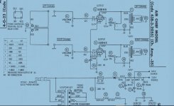
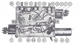
Here's another snip - it's the pic of the layout from the same SAMS page. I have replaced the 3 caps in the can - as usual they've gone bad. It removed the horrific loud noise that was present at all volume settings when I first got it. I've also replaced the three old paper caps with film caps of the same .05uf size. The 25uf 25V cap was replaced as well.
Attachments
Last edited:
Here's another snip - it's the pic of the layout from the same SAMS page. I have replaced the 3 caps in the can - as usual they've gone bad. It removed the horrific loud noise that was present at all volume settings when I first got it. I've also replaced the three old paper caps with film caps of the same .05uf size. The 25uf 25V cap was replaced as well.
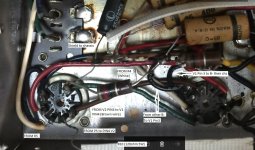
Wires from R4 and R5 to grids. They are not shielded, and go near filament wires.
The RCA plugs are soldered to the chassis right at the connection - if you look at the picture you'll see the two big solder points to the right of each RCA plug (there's more than one connecting point for the return besides the unoccupied return tabs). Mine looks pretty much exactly the same as the picture. I supposed I could try using wire to tap from the unoccupied tabs to the chassis to see if that helps.
It's possible it's the R4/R5 to grid wires, but then why do I have the mid-control hum so loud in one versus the other? Wouldn't that imply that this amp hummed loud in mid-control like this right from the factory?
Turns out I did indeed take a pic of this amp before working on it; the wirings the same with new caps (V2 is the tube at the left). I noted the different connections on this zoom view . I can see the white wire from R4 crossing under the power line tween V1 and V2 - but R4 is for the channel that has LESS noise mid-control. Any suggestions for shielding these wires? Maybe replace with different ones? I'm realistic in my expectations here - its's a cheap amp for the time, it'll never be noiseless, but I believe what I'm hearing is quite a bit more than what you'd expect from the factory.
Attachments
I just snagged some nice shielded phono cables - really phono and video as there are 3 pairs with first class phono plugs on each end - from a local thrift for a couple bucks with the intent of making better patch cords of them. However, I suspect I could use them for this as well. I'd just avoid putting two power cables into them and defeating the purpose of the shielding! ") Just want to be sure the plastic outer cover doesnt melt easily, it gets pretty toasty inside this amp (which hangs upside down in this suitcase portable when the turntable is flipped open in the front). I'll keep you posted on how this goes. I'm also working on the V-M turntable; it needs a cleanout so the platter doesnt need my help to get past helping the arm raise and move over to the record. Typical old gunky lubrication to clean out..
Just want to be sure the plastic outer cover doesnt melt easily, it gets pretty toasty inside this amp (which hangs upside down in this suitcase portable when the turntable is flipped open in the front). I'll keep you posted on how this goes. I'm also working on the V-M turntable; it needs a cleanout so the platter doesnt need my help to get past helping the arm raise and move over to the record. Typical old gunky lubrication to clean out..
Just want to be sure the plastic outer cover doesnt melt easily, it gets pretty toasty inside this amp (which hangs upside down in this suitcase portable when the turntable is flipped open in the front). I'll keep you posted on how this goes. I'm also working on the V-M turntable; it needs a cleanout so the platter doesnt need my help to get past helping the arm raise and move over to the record. Typical old gunky lubrication to clean out..> a very basic 50EH5 amp design
This is a HOT CHASSIS design. "Safe" ONLY if you can NOT touch the audio common (pickup or speaker wires). Or if an Isolation Transformer is properly installed. How do we know you won't get killed?
And yes: a 3Meg pot halfway up is sure to attract all the hum and buzz in the chassis. These amps were too cheap to complain about. I would not mess with one today.
Hi - I've been remiss in putting up an intro to myself that includes experience. I appreciate your concerns about the hot chassis and share them - I just got a Triad N-68X in the mail Friday that's being used on this project along with a power switch, fuse etc to make it a bit safer. In normal operation these chassis were enclosed fully without even an open back to allow fingers to get at them. I mess with them because I like to restore and collect these phonographs and such mostly-as-originally-designed, it's my hobby.
Also, when running well, some of these amps produce wonderful sound, low wattage be damned. I have restored an amp on a Magnavox Holiday portable record player that sounds amazing. It uses 2 50EH5s off a 12AX7. a couple of NOS 50EH5's, a new 12AX7, and replacing the capacitors brought the sound back to what I imagined it would have sounded like new. Maybe better.
As for the hummer, I did find a couple of projecting wires/leads connected to the 3Mohm volume POTS of the channel with the most noise, that were projecting beyond the solder point, clipping them reduced the noise quite a bit, so I am reviewing other connections for bad soldering or overlong exposed leads/wires as well. I did a survey of the resistances from each pin, based on the information from the SAMS page, and they're fairly close to spec (in that era 10-15% of spec is okay) - no very-low resistance measurements indicating a ground fault or short. I'm also looking into picking up shielding and shielded cable to replace the wiring inside where needed. I tend to stick to the schematic design (save safety improvements) but am not above using better materials when needed to get the design to work better.
One question, I'd like your opinion on: on most of these hot-chassis designs, they put a .05uf capacitor between the B- and chassis. I've read some articles saying not to use 3 wire cabling and the green wire to ground the chassis but to leave this as is. However, I've also seen other designs where they remove the .05uf between B- and chassis and then use the green ground wire to ground the chassis. In either case, the hot lead goes to the rectifier and filament strings, neutral goes to (usually) the lead into the record player where a switch resides turning the whole thing on and off when you start the changer.
Which way - with or without the caps floating the B- to the chassis - do you think is the better design?
- Status
- This old topic is closed. If you want to reopen this topic, contact a moderator using the "Report Post" button.
- Home
- Amplifiers
- Tubes / Valves
- Hum if volume control between midpoint and max; No hum if volume knob at max or zero