HI,
Need help calculating cathode follower! No idea how it's done!
Params:
Input levels: iPod, CD (1.2V~2.0V)
Load impedance: 3.3kOhm
Distortion as low as possible.
Anode power supply: +90V
Schematics:
My estimate values:
Cin = 2uF
Cout = 20uF
RL = 3 kOhm
RB = 200 Ohm
RG = 100 kOhm
I also searched over the internet in hope to find tutorials on how to calculate stuff, but it is just way over my head.
Will buy a beer to whoever helps! 😀
Need help calculating cathode follower! No idea how it's done!
Params:
Input levels: iPod, CD (1.2V~2.0V)
Load impedance: 3.3kOhm
Distortion as low as possible.
Anode power supply: +90V
Schematics:
An externally hosted image should be here but it was not working when we last tested it.
My estimate values:
Cin = 2uF
Cout = 20uF
RL = 3 kOhm
RB = 200 Ohm
RG = 100 kOhm
I also searched over the internet in hope to find tutorials on how to calculate stuff, but it is just way over my head.
Will buy a beer to whoever helps! 😀
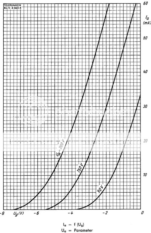
Working with what you have.. say 2vRMS input, is (x1.414) = 2.8V peak. So you need the grid to be at least -3V negative WRT to cathode.
That 90V needs to be distributed across both the tube and the cathode resistor/s, and
looking along the -3V bias line in the transfer curves, you need 90V across just the tube itself even at 1mA..
You really need a higher voltage B supply if the stage is to be ok with full 2vRMS input and not clip..
Shane
...So you need the grid to be at least -3V negative WRT to cathode...
Shane
Yes, if this were an ordinary common cathode stage with bypassed cathode resistor, but this is a cathode follower.
So the cathode is not at fixed potentia. It follows the grid voltage.
Even -1 V as Ug-k would be sufficient.
Last edited:
Is there a book that I can get and read so I will understand tube circutry? Something classical and essential?
Thanks
Thanks
R5 is so called grid stopper. It ensures that the cathode follower do not begin to oscillate at high frequencies.
Basic tube technics are explained in many places, here is one:
How to design valve guitar amplifiers
Basic tube technics are explained in many places, here is one:
How to design valve guitar amplifiers
Thank you guys for links!
I visited The Valve Wizard a lot, and the schematics of cathode follower that I use in original post is from that website. Thats why I started with 12AU7, but then found ECC88 that I think is able to deliver output impedance of ~76R vs 12AU7 ~402R (according to Cathode Follower Output Impedance Calculator)
Second link is promising as well.
Looks like schematics that artosalo provided is identical to the one for 12AU7 in other thread that I started http://www.diyaudio.com/forums/tubes-valves/263190-calculating-cathode-follower-using-12au7-90v-supply.html. Except load impedance and Cout - they are different. Thats a good news to me since I can easily try both ECC88 and 12AU7.
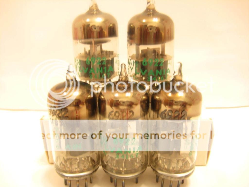
The other great news is that I was able to get two 6922 JAN Sylvania for $10 each on eBay, and same tubes cost each $50 here: https://www.tubedepot.com/products/jan-sylvania-6922
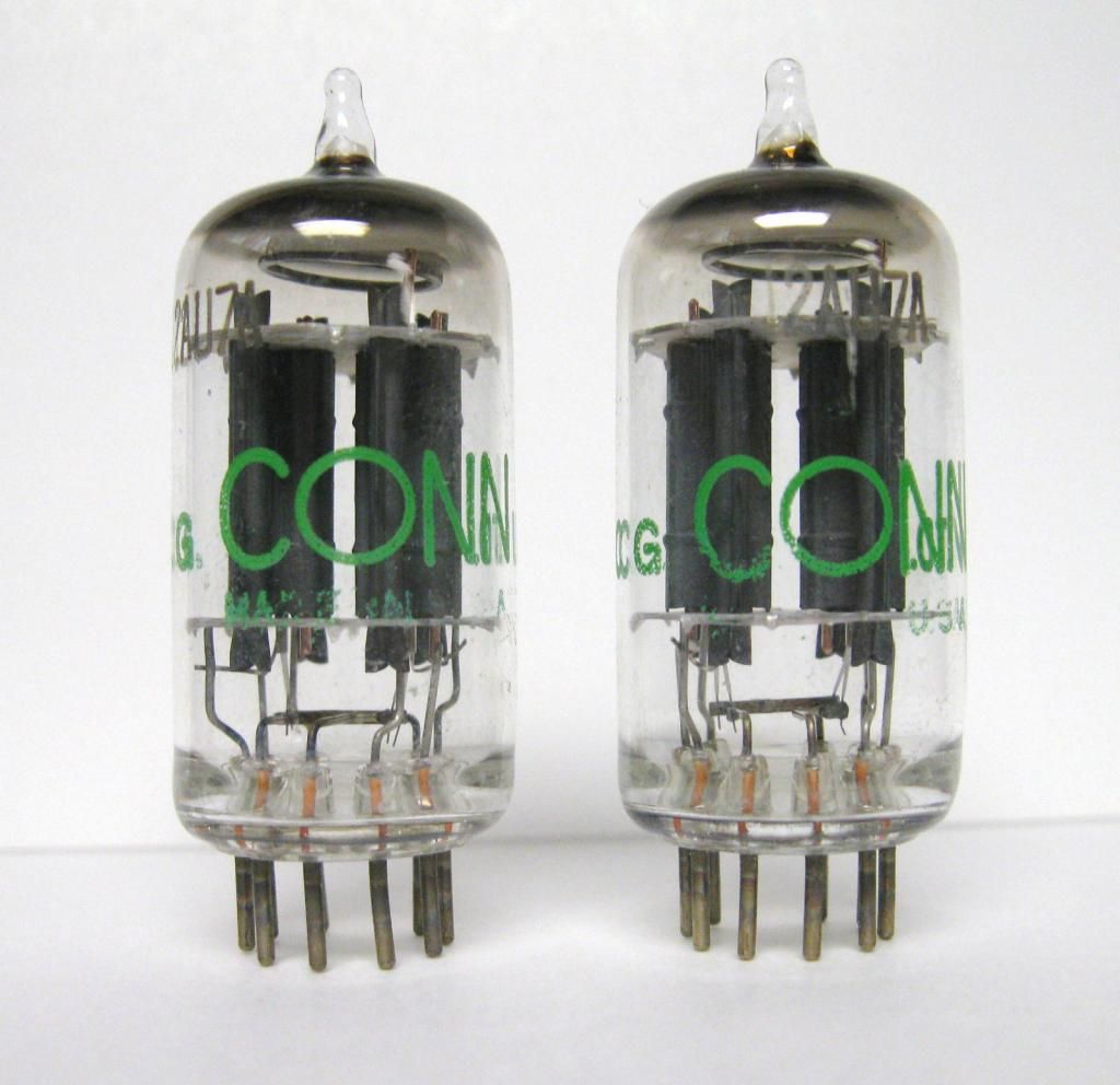
For 12AU7 I got two from old organ I think. According to Joe's Tube Lore the 12AU7 will have average sound and 6922 will sound much nicer. When I get them, I want to listen for myself and see if I able to hear difference.
6922
12AU7
I visited The Valve Wizard a lot, and the schematics of cathode follower that I use in original post is from that website. Thats why I started with 12AU7, but then found ECC88 that I think is able to deliver output impedance of ~76R vs 12AU7 ~402R (according to Cathode Follower Output Impedance Calculator)
Second link is promising as well.
Looks like schematics that artosalo provided is identical to the one for 12AU7 in other thread that I started http://www.diyaudio.com/forums/tubes-valves/263190-calculating-cathode-follower-using-12au7-90v-supply.html. Except load impedance and Cout - they are different. Thats a good news to me since I can easily try both ECC88 and 12AU7.
The other great news is that I was able to get two 6922 JAN Sylvania for $10 each on eBay, and same tubes cost each $50 here: https://www.tubedepot.com/products/jan-sylvania-6922
For 12AU7 I got two from old organ I think. According to Joe's Tube Lore the 12AU7 will have average sound and 6922 will sound much nicer. When I get them, I want to listen for myself and see if I able to hear difference.
6922
12AU7
An externally hosted image should be here but it was not working when we last tested it.
What the input impedance will be? Isn't it Rg / ( 1 - (Av * Rl / (Rl+Rb) )) ??????
Where Av = gain that is always <1
1,000,000 / (1 - 0.95 * (5600/(5600+390) )) = 8,940,299 = 8.9MOhm
Please, check if Im correct!
Where Av = gain that is always <1
1,000,000 / (1 - 0.95 * (5600/(5600+390) )) = 8,940,299 = 8.9MOhm
Please, check if Im correct!
Last edited:
OK, now I need to decide where to put volume control. It'll be 10K potentiometer with one leg to ground, other two legs for input and output signal +. Should I put it in front of cathode follower or after it?
What's better?
Thanks
What's better?
Thanks
Before cathode follower. If it were after, then the low output impedance of the cathode follower is lost.
Now I'm entering power supply fun zone!!!
Heaters:
I have transformer winding with ~7.3V. Current is unknown. I think 6922 filament current is 350mA? Not sure on that. Hopefully current from transformer will be enough. Should I put series resistor to drop voltage to ~6.3V?
Anode supply:
Things are complicated here. I have supply that delivers +30-0-30V. From there I am planning on using voltage multiplier:
And regulator like this:
Will it be safe to put input/output signal GND to power supply ground? Will the power supply work? I mean, there is no -90V supply, just ground?
Any considerations???
Thanks
Last edited:
- Status
- Not open for further replies.
- Home
- Amplifiers
- Tubes / Valves
- Calculating 6922/E88CC/ECC88 cathode follower for 90V anode