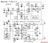
I bought a pcb of the musical fidelity x10d buffer clone. The circuit is well described on the net, but to be sure I attach it again.
My aim is to use this circuit to make myself a cheap tube preamp with gain and low voltage. First step is to change R206 (1k5, makes the amp has a gain of 1) into 33k so I have a gain of around 5 times.
I stuffed the pcb without problems, got a nice 12.5 Volt on the filaments and around plus and minus 30V for the 'high voltages' B+ and B-. I built the tubes in lying position with some extension of the wires (only 1-2 inches for some tube pins).
Lastly I built the pcb into an existing enclosure with inputs/outputs source select etc.
Now the problem. I get a rattling noise on both channels. What have I done?
- Tried all kinds of earthing scheme's. To no avail.
- Tried to change the feedback C into another value and even no C at all. It seems the amp is somewhat more quite without the C. Making it higher has no effect on the noises.
- For learning purposes I changed one channel into a cathode-follower as the second halve of the ECC88. Can be done with some minor changes. Without feedback altogether I get a gain of (I guess) around 2-3 (less than the other channel with 2x anode-follower and 33k feedback). But both channels have around the same irritating noise and back-ground rattling. So it seems the problem has nothing to do with feedback or oscillation?
- Aha, I thought, must be the rattling of a diode that goes right to the tubes. So I put a C of 10nF to get rid of spikes on top of D1 (that makes the filaments glow). Not the problem. I changed D1 for another one. No change.
I tend to give up. With this circuit it has to be dead quite. What can cause the problem? Maybe the other D's that make the plus/minus 30V? Only a few ma's there, so I think this is not likely the cause. The wires that pick up noise from elsewhere? Tried to change the dressing, no effect. Besides that: I once made the ECC82+mosfet circuit on +12v in the same enclosure and that one was dead quite without problems at all (why not use that one then? It only goes to .5V at the output).
Anybody who got a clue or a hint, thank you very much.
The noise is not a normal background hum (that is monotone). It has some frequency rattling component in it, both in high as in low frequencies.
Attachments
I have experimented with x10d clone for some time. Regardless the negative remarks you find on this board, I tell you that I like it and I liked working on it to improve its performance for the same purpose as yours.
Grid leak bias is not a kind praised much about I figured, but I like the sound I got from it.
What I did is as follows:
The gain is attained by the 1.5k feedback resistor AND the 8.2K resistor together, they both to be worked on.
I used a 25K x2 pot in place of that feedback resistor and changed the feedback cap parallel to it to 75pF.
I removed that 8.2K cathode resistor. In its place I used a red LED with a bypass cap of 470uF 16V Oscon type, in series with these a 10K pot for each channel.
Now you can play a long time(!!) to find a good combination in their values.
I have used external DC voltage sources for HT and the heaters. I went up to +/- 85V for the supply, but used the on-board current limiters, I did set them for slightly higher currents but I don't remember to what level, or if I left the circuit that way in the end though. I modified the heater traces, dropping out 2K(?) parallel resistors and other things that I don't remember much. But I used well regulated heater supply and I lifted the heater ground( actually in negative side, so not with respect to circuit ground) about 25v from the negative rail.
I did not use most of the filter electrolytics on board.
I used Russian PIO caps and Jantzen z-caps in the signal path.
I used Solen 10uF on the feedback line.
I played with the 56K anode load resistors to shift the op-point a little bit on the higher anode current side, but don't remember what value was the final. Similarly, 10k anode loads ended up at 20k I believe.
Each time I moved on to change something I worked on it until I was sure I got improved sound, otherwise changed it back to the old one.
One thing I can tell you that this circuit performs differently with different kind of tubes I you may try and see. I learned a lot about ECC88 variations and its equivalents, and of course it came with a budget side too, I ended up liking Russian 6N23P in this circuit.
Good luck!
- Status
- Not open for further replies.