Hello,
In trying to revive my knowledge of tube audio amplifier theory, I am currently solving the problems in a book dealing with vacuum tube fundamentals.
At this moment I am trying to solve problems in a chapter about phase splitters for driving a push-pull stage.
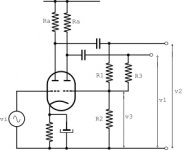
There is one particular problem which I did solve but, am uncertain if my answers are correctly executed. It concerns a so called 'plate follower' or 'anode follower' stage in a two stage phase splitter, where the first stage is a normal grounded cathode amplifier stage driving the second one which has this 'plate follower' configuration. Here is the circuit diagram and the data:
[FONT=Courier New, monospace]μ= [/FONT][FONT=Courier New, monospace]100[/FONT][FONT=Courier New, monospace]; [/FONT][FONT=Courier New, monospace]([/FONT][FONT=Courier New, monospace]gain factor)[/FONT]
Ri= 20k[FONT=Courier New, monospace]Ω; [/FONT]
[FONT=Courier New, monospace]R[/FONT][FONT=Courier New, monospace]a[/FONT][FONT=Courier New, monospace]= [/FONT][FONT=Courier New, monospace]80[/FONT][FONT=Courier New, monospace]k[/FONT][FONT=Courier New, monospace]Ω;[/FONT]
[FONT=Courier New, monospace]R1= [/FONT][FONT=Courier New, monospace]40[/FONT][FONT=Courier New, monospace]0k[/FONT][FONT=Courier New, monospace]Ω;[/FONT]
[FONT=Courier New, monospace]R[/FONT][FONT=Courier New, monospace]3[/FONT][FONT=Courier New, monospace]= [/FONT][FONT=Courier New, monospace]20[/FONT][FONT=Courier New, monospace]k[/FONT][FONT=Courier New, monospace]Ω;[/FONT]
[FONT=Courier New, monospace]v2=-v1[/FONT]
[FONT=Courier New, monospace]T[/FONT][FONT=Courier New, monospace]he author asks to calculate[/FONT]
[FONT=Courier New, monospace]the value of R2.[/FONT]
[FONT=Courier New, monospace]He also supplies the answer:[/FONT]
[FONT=Courier New, monospace]R2= 467[/FONT][FONT=Courier New, monospace]Ω, [/FONT][FONT=Courier New, monospace]but not how to calculate this.[/FONT]
[FONT=Courier New, monospace]Before I am bothering the forum with my solution of this problem I want to ask you if someone is willing to help me with checking my[/FONT]
[FONT=Courier New, monospace]solution... [/FONT][FONT=Courier New, monospace]If so, then I will translate my solution using the English language.[/FONT]
[FONT=Courier New, monospace]Thanks in advance,[/FONT]
[FONT=Courier New, monospace]Joe.[/FONT]
In trying to revive my knowledge of tube audio amplifier theory, I am currently solving the problems in a book dealing with vacuum tube fundamentals.
At this moment I am trying to solve problems in a chapter about phase splitters for driving a push-pull stage.
There is one particular problem which I did solve but, am uncertain if my answers are correctly executed. It concerns a so called 'plate follower' or 'anode follower' stage in a two stage phase splitter, where the first stage is a normal grounded cathode amplifier stage driving the second one which has this 'plate follower' configuration. Here is the circuit diagram and the data:
[FONT=Courier New, monospace]μ= [/FONT][FONT=Courier New, monospace]100[/FONT][FONT=Courier New, monospace]; [/FONT][FONT=Courier New, monospace]([/FONT][FONT=Courier New, monospace]gain factor)[/FONT]
Ri= 20k[FONT=Courier New, monospace]Ω; [/FONT]
[FONT=Courier New, monospace]R[/FONT][FONT=Courier New, monospace]a[/FONT][FONT=Courier New, monospace]= [/FONT][FONT=Courier New, monospace]80[/FONT][FONT=Courier New, monospace]k[/FONT][FONT=Courier New, monospace]Ω;[/FONT]
[FONT=Courier New, monospace]R1= [/FONT][FONT=Courier New, monospace]40[/FONT][FONT=Courier New, monospace]0k[/FONT][FONT=Courier New, monospace]Ω;[/FONT]
[FONT=Courier New, monospace]R[/FONT][FONT=Courier New, monospace]3[/FONT][FONT=Courier New, monospace]= [/FONT][FONT=Courier New, monospace]20[/FONT][FONT=Courier New, monospace]k[/FONT][FONT=Courier New, monospace]Ω;[/FONT]
[FONT=Courier New, monospace]v2=-v1[/FONT]
[FONT=Courier New, monospace]T[/FONT][FONT=Courier New, monospace]he author asks to calculate[/FONT]
[FONT=Courier New, monospace]the value of R2.[/FONT]
[FONT=Courier New, monospace]He also supplies the answer:[/FONT]
[FONT=Courier New, monospace]R2= 467[/FONT][FONT=Courier New, monospace]Ω, [/FONT][FONT=Courier New, monospace]but not how to calculate this.[/FONT]
[FONT=Courier New, monospace]Before I am bothering the forum with my solution of this problem I want to ask you if someone is willing to help me with checking my[/FONT]
[FONT=Courier New, monospace]solution... [/FONT][FONT=Courier New, monospace]If so, then I will translate my solution using the English language.[/FONT]
[FONT=Courier New, monospace]Thanks in advance,[/FONT]
[FONT=Courier New, monospace]Joe.[/FONT]
Attachments
Are you sure those numbers are correct??
The only way I can see it working is by reducing R1 to 4k instead of 400k. The massive feedback from R3 would swamp it otherwise. But the 4k would make it a horrible stage. The first triode gives an amplification of 80, but with such a load, it's reduced to about 3 or 4!
Or the given answer is wrong and should be multiplied by 1000, but than R3 should be altered to maintain balance between outputs. So... something's fishy.
Either you have misunderstood, or the author is wrong. The circuit with the component values you have given will not work.
For a plate/anode follower as a phase splitter you would need R1 and R3 to be about the same value, and R2 to be much larger than 467R.
For a plate/anode follower as a phase splitter you would need R1 and R3 to be about the same value, and R2 to be much larger than 467R.
I just use a single triode phase splitter as it is easy to understand.
The anode and cathode resistors are the same and the grid is set to 1/4 B+
The anode and cathode resistors are the same and the grid is set to 1/4 B+
Yes the 'cathodyne' or 'split load' PI is a nice stage, but not always applicable since is has no gain of its own (you'll need another triode) and looses its balance when unevenly loaded. Horrible when overdriven as well.I just use a single triode phase splitter as it is easy to understand.
The anode and cathode resistors are the same and the grid is set to 1/4 B+
I don't think the OP's intention is to settle with a certain PI, but to fundamentally understand the workings, and to mathematically solve, a given tube circuit.
Hello forum members,
Thanks for your responses and suggestions!
After having solved this problem for the first time I was also astonished about the extreme low value of the calculated R2. Which I did not expect.
Then I tried to solve it in a somewhat different way arriving at the same result. But I still I have the unpleasant feeling that 'something is wrong' here but cannot detect what is it.
So here the two pdf files with my solutions. Hope you guys can detect where I went wrong.
Now I got the idea to let LTspice calculate this R2 value but did not had the time to do so..
Joe.
Attachments
Either you have misunderstood, or the author is wrong. The circuit with the component values you have given will not work.
Actually the book is correct, a value of 467 ohms would give unity gain. Admittedly, it is a peculiar way to arrange the circuit.
I used a very quick 'n' dirty calculation:
First estimate the open-loop gain, noting that the load on the valve is roughly Ra||R3 = 16k.
A = 100 * 16 / (16 + 20) = 44
Now assume +44V at the anode, -1V at the grid and -44V input.
Current in R3 = 45/20k = 2.25mA
Current in R1 = 43/400k = 108uA
Therefore current in R2 = 2.25 - 0.108 = 2.142mA
Since there is 1V across it, its value must be 1/2.142mA = 467 ohms.
Last edited:
Think again.
R1 provides the input signal current for the inverter. 400k feeding around 467R gives an attenuation worse than 0.001. Times the stage gain of -44 you get around 0.04 gain from anode to anode, before you add the negative feedback. You should have checked your arithmetic for plausibility. A plate/anode follower will have similar signal currents in the input resistor and feedback resistor - yours does not. It will also have similar values for the input and feedback resistor - yours does not (n.b. if gain is required then the feedback resistor will be larger than the input resistor - yours is much smaller!).
Assuming a circuit works, and then doing the arithmetic to get component values, is a valid way of analysing provided that the assumption is correct. You have mixed up feedback current and input current.
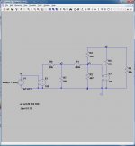
Ok, all theory aside, LTSpice says no-go.
funk1980,
Look at this LTspice diagram, especially the second voltage source.
Then run this and look at the results.
How about some comments on my pdf's?
Attachments
I tend to look at it the same way as DF96. Treating it as two separate stages. Two common cathode stages with a voltage divider in between and some feedback.
I've simulated the given schematic and it gives exactly the same results as my triode/caps simulation. Bit of a relief 😀. Your E3 has its polarity reversed by the way. It's still an inverting stage.

Concerning the PDF's, I'm not the guy to comment on them. It's more theoratical then I'm used to work with. I do see a lot of building upon previous transformations and calculations and am worried something might have gone 'lost in translation'.
I've simulated the given schematic and it gives exactly the same results as my triode/caps simulation. Bit of a relief 😀. Your E3 has its polarity reversed by the way. It's still an inverting stage.
Concerning the PDF's, I'm not the guy to comment on them. It's more theoratical then I'm used to work with. I do see a lot of building upon previous transformations and calculations and am worried something might have gone 'lost in translation'.
Last edited:
My LTspice give results as below:
An externally hosted image should be here but it was not working when we last tested it.
My LTspice give results as below:
An externally hosted image should be here but it was not working when we last tested it.
Yes, completely compliant with my results. JoeAlders will have a bit more amplification due to the reversed E3, but still, V2 will have nowhere near as high an output as V1.
You have used A0=44, it should be -44. The stage inverts.JoeAlders said:How about some comments on my pdf's?
funk1980 wrote:
'I tend to look at it the same way as DF96. Treating it as two separate stages. Two common cathode stages with a voltage divider in between and some feedback.'
That is exactly what I did in my two pdf's.
'I do see a lot of building upon previous transformations and calculations and am worried something might have gone 'lost in translation'.'
Do not know what you mean by this 'building upon previous transformations'
What is previous? Do you mean I left something out of the original Dutch version? If so, I am willing to also publish my Dutch original if this will help clearing things up.
About LTspice: I must confess that I am not an expert on this, so I have to rely on the experience of you guys on this forum.
DF96 wrote:
'You have used A0=44, it should be -44. The stage inverts. '
I will do a recalculation with this. But you are correct.
Joe.
funk1980 wrote:
'I tend to look at it the same way as DF96. Treating it as two separate stages. Two common cathode stages with a voltage divider in between and some feedback.'
That is exactly what I did in my two pdf's.
Indeed, but look at it from a more logical standpoint then. The second common cathode stage, with the same anode load but with feedback (so less amplification), should have a bigger input than the first to give an equal output, yet it has a voltage divider in front of it with a ratio of 0,0012. The amplification of the first stage is 44, so the divider ratio should be more than 0.022.
'I do see a lot of building upon previous transformations and calculations and am worried something might have gone 'lost in translation'.'
Do not know what you mean by this 'building upon previous transformations'
What is previous? Do you mean I left something out of the original Dutch version? If so, I am willing to also publish my Dutch original if this will help clearing things up.
What I meant was, you go from the original schematic -> AC variant -> hacked in two -> redraw -> Thevenin -> Alternate Thevenin -> etc. with several formulas based on each redraw. Loooots of places for errors with a snowball effect to the final solution. Not saying it's wrong, on the contrary, I applaud your drive and ability to treat a stage this way, but again, a small error in the beginning will have big implications later on.
Edit: Come to think of it. You hack the schematic in two and forget about the first stage entirely it seems. But the impedance of the first stage is always in parallel with R1 and R2, yet it's ignored.
Last edited:
We can ignore the impedance of the first stage because all we require is that the second anode follows (with inversion) the first anode.
What seems to have happened is that there are two 'solutions' to this circuit. The first is the normal solution, with roughly equal input and feedback resistors and a biggish resistor to ground to provide grid leak. The second 'solution', given by the author and found by the OP, is based on the stage not inverting so the feedback becomes positive so huge stage gain requires a lot of attenuation. Somehow a phase inversion is sneaked into the circuit (but not the maths) - the second 'solution' could be politely called the 'unphysical solution' by a physicist although it is actually just wrong.
What seems to have happened is that there are two 'solutions' to this circuit. The first is the normal solution, with roughly equal input and feedback resistors and a biggish resistor to ground to provide grid leak. The second 'solution', given by the author and found by the OP, is based on the stage not inverting so the feedback becomes positive so huge stage gain requires a lot of attenuation. Somehow a phase inversion is sneaked into the circuit (but not the maths) - the second 'solution' could be politely called the 'unphysical solution' by a physicist although it is actually just wrong.
I see what you mean, my logic failed me on that one. I thought the divider was also dependent on the load it placed on the first stage, but with a heavy load, and therefor less output from V1, V2's signal needs to reduce as well. Cheers.We can ignore the impedance of the first stage because all we require is that the second anode follows (with inversion) the first anode.
In trying to get to the bottom of this circuit I simulated the whole circuit using the
constant current source equivalent circuit.
And after letting LTspice calculate v1/v2 I find a striking difference in results with respect to the result when using a constant voltage source.
I certainly made a mistake here. Can somebody tell me where please?
constant current source equivalent circuit.
And after letting LTspice calculate v1/v2 I find a striking difference in results with respect to the result when using a constant voltage source.
I certainly made a mistake here. Can somebody tell me where please?
Attachments

Do you now have inverting amplifiers? Because of the feedback around the second stage a sign error will make a huge difference in gain.
PS why bother to solve the wrong circuit? Why not look at a circuit which will actually work?
PS why bother to solve the wrong circuit? Why not look at a circuit which will actually work?
Last edited:
- Status
- Not open for further replies.
- Home
- Amplifiers
- Tubes / Valves
- Trying to solve a Plate Follower Problem