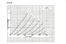
I want to know how a 12AT6 will operate below 100VDC on the plate. The tube data sheet graph (attached) barely lets me plot 108VDC vs 0.20 mA (what I have running currently on a circuit I am working on). There must be some assumptions made to get the data plotted (lines for various grid voltages), such as plate load, input impedance, etc. Some data sheets list example operating conditions and spec a "plate resistance", or a "cathode resistance", but these are for one set of conditions.... What are the standards used to create these plots? Thanks!
Attachments
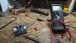
Well I got started anyway...! 12AU7 with 0-290VDC B+ available on a big Ohmite slider, variable cathode 5Kohm bias pot (to dial in grid voltage lines on tube data graph), 68K plate load, and 1Meg grid input (to ground). Measured plate VDC, dialed in -2.0 volts on grid, calc'd plate current thru plate load..... Got 1.25mA, data sheet predicted 1.5mA. Close but expected better... changed grid resistor to 5Meg, values changed, but even with cathode grounded couldn't get lower than -3V (with respect to cathode, correct?). Back to drawing board...
Attachments
The graphs are plotted for the configuration stated - so many volts on plate, so many volts on grid, and with these the tube determines the plate current. Things outside the tube like resistance in series witrh the plate, grid resistance, etc have nothing to do with it. It's just a more complex situation than grabbing a certain resistor and applying a voltage across it. You get a certain current and that's it.
To design for conditions at very low plate currents (which mean a high bias voltage unless the tube is stuffed), you need a bit of basic mathematics. The current in a triode follows the "three halves power" rule. That is, the current is equal to:-
Ia = k x Vak^(3/2)
where k is a constant that depends on the dimensions and placement of the structure within the grid, and the grid voltage. So if yoiu find a value of k that fits a given curve on a graph of playte curves (Ia versus Vak), that value will be valid for all values of plate current well below the cathode's emission capability.
The formula breaks down near and below zero bias, but that is immaterial to your situation.
Very high values of grid resistance lead to lower than expected palte currents due to cathode sapce charge. Electronics impinge on the grid, driving it negative. So if the external leak resistance is high, this negative charge on the grid can't drain away. You can't measure this charge with an ordinary multimeter as the meter will drain away the charge.
Keit
Last edited:
Some data sheets list example operating conditions and spec a "plate resistance", or a "cathode resistance", but these are for one set of conditions.... What are the standards used to create these plots? Thanks!
Those operating conditions in the datasheet are examples of how the tubes can be used, BUT they are not the conditions used to generate the plate characteristic curves, here is a very simple manual curve tracer using off the shelf parts, you can ignore the G2 supply when tracing triode curves:
Simple curve tracer courtesy of PRR:
An externally hosted image should be here but it was not working when we last tested it.
Keit - I will definitely look into that "3 halves power" rule, and appreciate leaning how unseen tube nuances affect the tubes response.
Jazbo - I see the PRR circuit biases the grid with batteries. Will try that method (was just raising cathode potential with a pot). I was having trouble getting a solid zero grid voltage.
Thanks!
Jazbo - I see the PRR circuit biases the grid with batteries. Will try that method (was just raising cathode potential with a pot). I was having trouble getting a solid zero grid voltage.
Thanks!
The 3/2 rule can break down at low anode currents too. Don't assume it when measuring a valve. Instead, do the measurements and then afterward see if the rule applies.
Errr... Yes it can. Actually, the rule still applies, but at very low currents, things link imperfections in the regularity of the grid wire turns, electron leakage at the top and bottom, and leakage of micas due to contamination make cut-off more remote than the math predicts.
Note that with biasing by means of a resistor in series with the cathode, cutoff at an anode voltage of ~100 volts occurs somewhat about 3 volts. Therefore this form of biasing cannot bias in excess of 3 volts. You cannot develop a voltage across a resistor unless there is current through it.
If you need to operate a tube at very low anode currents, don't use cathode resistor bias, as the current you get isn't set at all precisely.
- Status
- This old topic is closed. If you want to reopen this topic, contact a moderator using the "Report Post" button.
- Home
- Amplifiers
- Tubes / Valves
- Making a custom tube characteristic graph