I have a couple of large power amps I salvage from the junk pile years ago. They were in good condition, but were incomplete with a few pieces missing. I did find the manufacturer and came up with the schematic. I got them running and have used them for some time, but there has always been a bit of confusion on my part concerning the output transformer connections. The schematic shows an impedance changing plug, but these amps didn't have the complete system intact. The schematic shows the windings wires numbered but there was no terminals on the amps, and only colored wires. The primary connections were intact. One of the secondary windings has alway puzzled me.
Maybe someone could give me some insight concerning the output transformers. I have used an ohm meter to check the coils, which colored wires make up each pair on the secondary side. On the secondary side there are six coils. Four for the output and two for feedback. The schematic shows there should be 12 wires, two for each coil. The two feedback coils(3 smaller wires) are internally connected on one end such that only three wires exit to the outside. That internal connection is one of the wires and is grounded, each of the other ends of these two coils come out making up the three wires. No problem with that, it works and matches the schematic(sans the numbered terminals).
Now for my dilemma. The other four coils make up the rest of the wires, that is NINE wires! Three of the coils are straight forward, two wires with about 0.4 ohm readings. Each coil has a solid colored wire and a matching similar colored stripped wire. The last coil has three wires(?). Two solid colored(gray and black and a stripped wire(black with yellow strip). I have assumed that this was a center tapped coil as I have measured 0.8 ohms using the gray as a reference or center tap and twice this(1.6ohms) between the black and black/yellow. These two connected parallel would give an additional 0.4 ohm coil(not likely). Then all four coils are connected in parellel for an 3.75 ohm output tap, this according to the schematic. What I can't get my head around is how this 3 wire coil works???? All the coils appear to have the same size wire, making this odd coil having to have four times the number of windings(length of wire) as it measures 1.6 ohms end to end....... or 0.8 ohms each end to the center tap. Of course, using dc resistance is not the best way to determine connections like this, but does this make since? Any Ideas? Wouldn't one of the coils have to be wound backward to keep the polarity of the paralleled coils additive, referenced to the center tap? . I have connected a scope to the windings and tried to apply a small ac signal to the primary(50 ohms dc resistance), but there is to much high freq noise picked up such that the tiny signal on the secondary is swamped out. What is the easiest way to check polarity of these windings.
Attachments
If you have a variable auto former (a variac) you can set it to output some reasonable amount of voltage (like 50 VAC) and hook the leads to the top and bottom ends of the primary. Then pick two secondary windings for which you want to determine polarity relationship. Using your volt meter set to measure AC volts, measure the voltages of each secondary separately. Now connect the two secondaries in series and measure the voltage across the remaining two leads. If the voltage you now measure is the sum of the voltages of the two windings you measured previously, then the secondaries are connected together in normal polarity relationship. If the voltage is the difference of the two voltages you measured previously, then the two windings are connected in reverse polarity relationship.
You can continue with this procedure to determine the polarity relationship of all of the secondary windings.
You can continue with this procedure to determine the polarity relationship of all of the secondary windings.
Last edited:
Thanks for the Idea. I do have a variac and an old scope, so that could be done. I understand the concept concerning the use of the scope for both phase and amplitude checking as you suggest. My only concern is using a power source like a variac for signal input. I guess as long as there is no load connected to the secondary coils, the current thru the primary would be limited, correct? I could put in a 100ma fuse in the variac to limit the current.
Ok, I input about 30vac into the primary and got 2vac peak to peak on each output coil. I then series the coil one by one and each added 2vac peak to peak to the signal. When I added the last "odd 3wire coil" I first used the gray and Black/yellow as a pair, then the gray and black as a pair and each had the same result. They both added 2vac peak to peak to the signal for a total of 8 volts peak to peak for four coils, as expected. I then combined the black and black/yellow together and tried this out and had exactly the same result as if the black and black/yellow were the same wire. However, there is 1.6 ohms difference between these two wires, therefor they cannot be the same wire!!!!!!
Any Ideas on this. I also connected the scope between these two wires, and could not see any signal between these two, even on the 10 mv scale, sans noise. I'm lost here.
Any Ideas on this. I also connected the scope between these two wires, and could not see any signal between these two, even on the 10 mv scale, sans noise. I'm lost here.
Actually, your test results make perfect sense if you are measuring AC volts between 8(7) and 6(13) [i.e., the voltage across the pot, if the pot were wired in]. The connection of 7(8) to (6)13 puts the two winds in opposite polarity with respect to each other, so that AC voltages cancel, while still measuring a good amount of DC resistance between the same two leads.
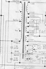
Ah, so you have the schematic too. Did you get them from this website or are you in possession of one? Well what ever, you are looking at the tertiary feedback windings and these small coils are not in question. The "odd coil" I am working with is the top right hand side of the transformer diagram. It is one of the power output coils. The schematic shows 4 each, two wire coils, but in real life one of those coils has three wire. At least there is continuity between the three wires. The other coils are white with white/black, green with green/yellow and yellow with red/ yellow coded wires. The fourth coil is, now get this, black or black/yellow paired with a gray. Yes, the strip now becomes the polarity mate of the other three solid colors!!!!! That is if I disregard the solid black. This is the mystery. You can use either the black and gray as a pair or the black/yellow and gray to make the fourth coil, or you may combine the black and the black/yellow with the gray and still get the same result. However there is 1.6 ohms between the black and the black/yellow and 0.8 ohms between each of these and the gray. And to top that off, the other coils measure 0.4 ohms, but add the same to the output as the "odd coil". There is however no signal developed across the black and black/yellow. I ask, could they be cancelling each other out, but yet they both will add to the other coils without changing polarity???
Still Lost here......
Still Lost here......
It appears that the black, gray, and black/yellow leads are connected to an internal wind where black and black-yellow are the "ends" and grey is the "center tap" except that the internal halves are connected in opposite polarity.
If you get signal between gray and black, and also between gray and black/yellow, but not between black and black/yellow, it supports that theory. Also you measure 0.8 ohm from grey to each end, and 1.6 ohms across the entire wind, which also supports this theory.
Color scheme wise, this conforms to the other winds (solid and solid-stripe match up). The difference on this last one is that grey wire which behaves like a center tap on that wind.
I haven't said anything you don't know already other than to point out that it sure "smells" like grey is behaving like a center tap.
That's the best I got.
could they be cancelling each other out, but yet they both will add to the other coils without changing polarity???
Try adding to another coil in both polarity orientations. Meaning, try and connect the grey and black wind in series with another wind, say white and white/black, measure voltage across the series combination of those winds, then reverse the grey and black connections and you should measure either more or less voltage. Then you could do the same with the grey and black/yellow and find that it behaves the same exact way. This will prove our little theory.
Of course, you've already proven the theory by knowing that measuring signal between black and black/yellow produce no signal, but it's a double check that each half of the black, grey, black/yellow wind work as expected.
Last edited:
Yeah, this just keeps getting stranger by the min. I did that, I connected this odd winding both ways with the others to insure that I got the polarity correct. One way it added to the volts out, and nulled out the volts with the connections reversed. I thought I did this with both the combinations. That is with the gray connected to a strip of another coil and one at a time using the black and then the black/yellow. I now quiestion my memory, but I thought that both acted the same way, both added or subtracted with the same orientation. However, I just got done connecting all the windings together with what I thought was the correct polarity with both the black and the black/yellow together on one side and the gray to the other and bad juju comes out thru the speaker. I will have to go back and retry getting the polarity correct, but I though I had it right. With the polarity reversed on this winding with the other three, it sounds ok. Maybe I should have someone look over my shoulder to keep it straight. Right now I thought I had it correct, but everything says I'm wrong.
Now, for our dilemma.... You need to give us (people on this forum) all the info you know about this amp. Like who manufactures it, what the model number of the amp is, what output tubes does it use and how many output tubes. This would be a huge help to us, so we can help you.
8, (7) & 6, (13) are probably your feedback windings. The 1K pot attached is most likely a damping factor control. If you put 30volts across the primary, what voltage comes out of EACH of these two windings? If you tell me that, I can guesstimate the impedance of these windings.
Now, according to your measurements, if you input 30 volts across the ENTIRE primary and got 2 volts out of each of the regular secondary windings, then the primary impedance of the transformer is approx. 787 ohms, which doesn't seem right unless these amps have around 8 output tubes each. And that is if each of these secondaries is a 3.5 ohm output winding.
Please get back to us with the information I ask. Also, please measure the voltages (primary & secondary) again with 30 volts across 1 and 5, the entire primary. These measurements have to be exact, not approximations.
Thanks.
I have a couple of large power amps...
Then all four coils are connected in parellel for an 3.75 ohm output tap, this according to the schematic.
These are 4 3.5 ohm windings that are connected in some form of series/parallel to get the output impedance required. All 4 windings in parallel will give you a 3.5 ohm output impedance. All 4 windings in series will give you an output impedance of 60 ohms. All 4 windings in series parallel will give you 15 ohms output impedance.
I think the problem is that you are thinking about this in terms of voltage / DC ohms, not in impedance. Impedance calculation is tricky when dealing with transformers.
The other 2 windings, 8, (7) & 6, (13) are most likely feedback windings that work with the amp circuitry to reduce distortion at the output. Most likely, they don't connect to the output of the amplifier. Transformers made this way are usually of very good quality.
Last edited:
I was just trying to help the OP as he stated he had wire colors but no terminal #'s
I have 3 different versions of the amp but no schematic and was trying to help.
These amps have 8 EL34 output tubes.
Tom
No, I think I have a reading comprehension problem... I didn't understand the OP's question. My fault. My snideness wasn't directed at you. When I first read his post I didn't see any identifying info about the amp. I thought somebody could give him info if that was known. My apologies for coming off as a jerk; also towards the OP. Sorry.
What amplifiers are these? They look interesting. Who makes them? Model #?
I guess 787 ohms primary impedance is about right for 8 EL34 output tubes. These amps are monsters!
Edit: I found this:
http://www.diyaudio.com/forums/tube...ation-pa-250ac-lab-grade-audio-amplifier.html
Last edited:
- Status
- This old topic is closed. If you want to reopen this topic, contact a moderator using the "Report Post" button.
- Home
- Amplifiers
- Tubes / Valves
- Another Output Transformer Wiring Question