It seems there are some interests for amplifiers made with 'sweep' tubes. I have made a real workhorse for 30years ago. It happend because via my job as a TV & Radio repairman felle in love with PL519A and the exspired EL503. I thought that one day I would like to hear this big power tube play music and I have never regret that. When this regards an existing and well proven amplifier it might have its own thread.
If not...delete it....
I have no schématic (only in my head) but it goes like this...

Many different tubes can be used here except for the output that has to be PL519/509 or similar. The driver and input is ECC85 and I asume that most peoble know how to find af propriate plate resistor to any tube. I ALWAYS seperate the power supply for the small tubes from the big ones. I want a stable supply for the smal tubes. I even use a stabelized for the input.
The output tubes run on 300V (3000uF) and the bias is ca -83V (100mA)...that means that the driver should be able to deliver least 200Vpp. To do this it need 430V supply because it loses 90V over the cathode resistor. Its conected to the input without coupling capacitor because I found that gives a more stable amplifier at full throttle. The output transformer must have an load impedance between 1600 to 1900ohm and be able to handle 100W at 30 HZ
I make the 430V by a voltage doubler from a 160V winding which also supply the output tubes filament; 40V X 4 = 160V...but the new amplifier I am building now are using EL509JJ. Thast means the new power transformer has a 6,3V 10A winding.
I also want to try another driver ECC99....
Why I use Ultra Linear coupling
Because it gives an output impedance on 0,8ohm and a damping factor at 10...before feedback is applied. When..feedback which is only 12db is applyed...then the damping factor increase to 40 which I am very satisfied with. When/if tetrode coupling are used it would be impossibly to get this prober output impedance...not even with 25db feed back.
I am aware that PL509/519 are scarce by now...but EL509-JJ is a VERY good replacement and made for audio. I call my amplifier for; *THE FINAL AMP* because I have never wanted any other amplifier. My friends claim the same..
Oh yes...it delivers 85W at 0,3% distortion and can run ANY loudspeaker...no need for 4, 8, 16 ohm tap here...thats one of the reasons I created this amplifier ... no speaker is only 4 or 8ohm or anything else. Therefore, an amplifier should do it all unchallenged. This leads to the sound...
The sound
This amp's ability to produce energy is very strong. Drum rim shot causes you to blink ... chorus makes you cry ... it come out as if you were present when the music was created. This makes this amp special ...
If anyone plan to built this I reccoment hard wiring as these amplifiers tends to last loooong...curcuit boards don't.
If not...delete it....
I have no schématic (only in my head) but it goes like this...
Many different tubes can be used here except for the output that has to be PL519/509 or similar. The driver and input is ECC85 and I asume that most peoble know how to find af propriate plate resistor to any tube. I ALWAYS seperate the power supply for the small tubes from the big ones. I want a stable supply for the smal tubes. I even use a stabelized for the input.
The output tubes run on 300V (3000uF) and the bias is ca -83V (100mA)...that means that the driver should be able to deliver least 200Vpp. To do this it need 430V supply because it loses 90V over the cathode resistor. Its conected to the input without coupling capacitor because I found that gives a more stable amplifier at full throttle. The output transformer must have an load impedance between 1600 to 1900ohm and be able to handle 100W at 30 HZ
I make the 430V by a voltage doubler from a 160V winding which also supply the output tubes filament; 40V X 4 = 160V...but the new amplifier I am building now are using EL509JJ. Thast means the new power transformer has a 6,3V 10A winding.
I also want to try another driver ECC99....
Why I use Ultra Linear coupling
Because it gives an output impedance on 0,8ohm and a damping factor at 10...before feedback is applied. When..feedback which is only 12db is applyed...then the damping factor increase to 40 which I am very satisfied with. When/if tetrode coupling are used it would be impossibly to get this prober output impedance...not even with 25db feed back.
I am aware that PL509/519 are scarce by now...but EL509-JJ is a VERY good replacement and made for audio. I call my amplifier for; *THE FINAL AMP* because I have never wanted any other amplifier. My friends claim the same..
Oh yes...it delivers 85W at 0,3% distortion and can run ANY loudspeaker...no need for 4, 8, 16 ohm tap here...thats one of the reasons I created this amplifier ... no speaker is only 4 or 8ohm or anything else. Therefore, an amplifier should do it all unchallenged. This leads to the sound...
The sound
This amp's ability to produce energy is very strong. Drum rim shot causes you to blink ... chorus makes you cry ... it come out as if you were present when the music was created. This makes this amp special ...
If anyone plan to built this I reccoment hard wiring as these amplifiers tends to last loooong...curcuit boards don't.
Last edited:
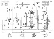
Good job Tubemania....your schematic (very close to a Mulard 5-20) is one i favor lately, very simple..
i like your design approach....😀
i like your design approach....😀
Thanks...both...
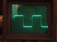
Here is my amplifiers square wave response....i am not a square wave fanatic however I use it to provoke my amplifier to see if it make somthing weird.
BTW; Did you guys know that a sweep tube are able to produce 2,5A (2500mA). I have done the exsperiment. My amp have a current about 25A...if nessecerry..
Yes, that's the tried and very true Mullard circuit. It's "classic" for good reason. It can be improved by replacing the phase splitter's tail resistor with a constant current sink (CCS), which forces symmetry between the 2 phases. The 10M45S integrated circuit is quite adequate for this job.
Have you played with a phase compensation cap. in parallel with the NFB resistor? You might be able to get a "better looking" square wave. FWIW, I think optimizing for 2 KHz. works well. Don't expect miracles, when 10 KHz. square waves are applied.
Have you played with a phase compensation cap. in parallel with the NFB resistor? You might be able to get a "better looking" square wave. FWIW, I think optimizing for 2 KHz. works well. Don't expect miracles, when 10 KHz. square waves are applied.
I had no knowledge about that particular curcuit...mine came out after severel try and errors...at last it met my demands...however I am glad that it is a classic curcuit...maybe thats the reason it works so well. It took me 2 yers to make it work as I wanted.
I am aware about the fasesplitter symmetri...however due to a large value for he cathode resistor not much to get there.There is no compensation capacitor because the tubes an the output tranny rolls of together. I am satisfied with the squarewave and the amp is bandwith limited to 70Khz.
I forgot to mention...the square wave shown is 10Khz
Last edited:
I forgot to mention...the square wave shown is 10Khz
That's pretty darned good.
Please post a complete schematic, when you can.
For completeness sake, I've uploaded the Mullard 5-20 schematic.
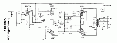
The best "vintage" implementation of Mullard style circuitry that I'm aware of is the Harman/Kardon Citation V. High gm types in the small signal circuitry provide protection against slew limiting induced by the GNFB HF error correction signal. I've uploaded the Cit. 5 schematic too. An ECC99 in the phase splitter role is (IMO) an obvious improvement.
Attachments
The square wave is highly dependent from the output transformer quality and from other factors too , below is the 10KHz square of my Futterman OTL PL36 amplifier onto 8Ω load ( without any compensation circuit or capacitor ) , it seems more like a square wave of an transistor amplifier .
Attachments
I had no knowledge about that particular curcuit...mine came out after severel try and errors...at last it met my demands...however I am glad that it is a classic curcuit...maybe thats the reason it works so well. It took me 2 yers to make it work as I wanted.
I am aware about the fasesplitter symmetri...however due to a large value for he cathode resistor not much to get there.There is no compensation capacitor because the tubes an the output tranny rolls of together. I am satisfied with the squarewave and the amp is bandwith limited to 70Khz.
I forgot to mention...the square wave shown is 10Khz
i am a big fan of TV tubes....
not to bring you the bad news, just about every amplifier topology
has been discovered years and years ago by those who came before us...😀
but there is no shame in that...😉
i consider the Mullard 5-20 has only 2 stages of gain, the Williamson had 3 stages....
my take is that with tubes, less is more, the sooner you can bring
the input signal to the output tube grids, the better..
having said this, i would like to try the 6BN11 LTP in my next builds...😀
can you share more info about your OPT? without giving out details,
can you tell what size cores you use, center leg vs. stacking height,
what type of material, i assume that you are using GOSS iron
and what is the thickness of laminations?
That's a pretty good shape. No ringing whatsoever. Darn good transformers!I forgot to mention...the square wave shown is 10Khz
I still have a pile of used PL519s. Maybe when my Dynaclone finally behaves I'm gonna give them a try and see if I can find a nice matched quad. Could be a problem as a K7 color TV ate through them back in the late seventies...
That's pretty darned good.
Please post a complete schematic, when you can.
I would like to see the FINAL schematic also. 😉
Resurrecting an old topic for a good cause ... I built an amplifier having inspired in this current topic, using PL509, but applying the 105V into G2 instead of 150V or something higher (and the pre stages differ: are more Marantz 8 like). Even with only 105Vg2, is obtained easily more than 60Wrms over the 320V B+ and 1k5 output transformer. Good thing is the bias now: only -19V! I use CFB instead of UL due my toroidal trafos, projected for CFB. Output power is limited only to G2 current, due to my simple VR105 gas regulator (serves to protect G2 from excessive dissipation). Most PL509 I measured have very low Ig2, about 1 to 2mA when anode are with 100mA! 100:1 ratio... Fantastic! (and I have an an spare RSD tube has 600µAg2 with 110mA/310V into anode...) Try to measure it with an EL34....
THD are 0,2% with 8W output, only 2H and 3H, and less than 0,05% at 1W. This thing are operating in open loop. DF = almost 1 (good for high efficiency speakers).
Probably this will also be my "final" amplifier, because it knocked things like SIT PP (the beast with hundreds supplyes) and the SE SIT I built, and it sounds more natural than my 300BSE, and have so much power (sufficient to my deafening) with an 94dB/2,83V/m TQWT (project by Troels Gravesen) loudspeaker! And if I need more damping factor to another speaker, I put some negative feedback on them.
If you ask me whether to mount an amplifier with PL509? I will say with certainty that yes!
Note that PL509 who have Barkausen plates/anodes support only 33W for anode dissipation, and those who do not have support 60W without red-hot the anode.
hello all ,
good job , i my build small OTL 2 EL 509 ( 1 for way ) and 1 ECC 82 , power max is +/- 700 mW to 8 Ohms .
i use to sound for me computer .
thank for up the thread .
good job , i my build small OTL 2 EL 509 ( 1 for way ) and 1 ECC 82 , power max is +/- 700 mW to 8 Ohms .
i use to sound for me computer .
thank for up the thread .
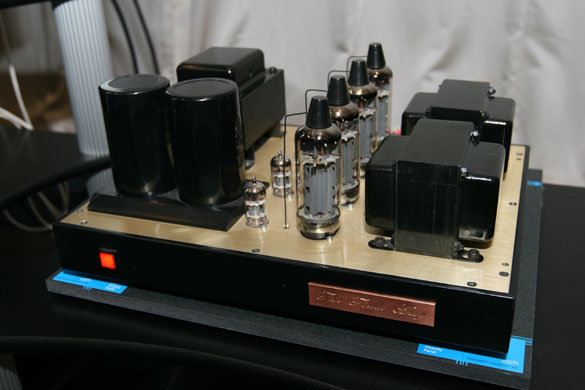
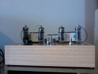
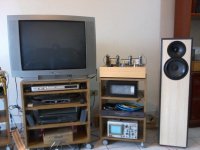
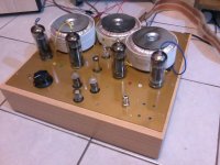
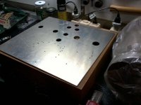
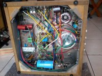
Some photos...
Some photos from my PL509PP
Jean Michel, the very high perveance from PL509 helps to make OTL and also low impedance/high power traditional transformer coupled, like mine and from Tube Mania; great tube!😎
Some photos from my PL509PP
Jean Michel, the very high perveance from PL509 helps to make OTL and also low impedance/high power traditional transformer coupled, like mine and from Tube Mania; great tube!😎
Attachments
-
 2015-05-30 10.20.55.jpg73 KB · Views: 172
 -
 2015-05-30 10.20.07.jpg82.1 KB · Views: 311
 -
 2015-05-24 20.14.42.jpg85.1 KB · Views: 315
 -
 2015-05-04 19.23.37.jpg81.5 KB · Views: 301
 -
 2015-04-28 21.11.12.jpg78.6 KB · Views: 294
 -
 2014-09-20 16.33.27.jpg107.6 KB · Views: 305
 -
 2015-05-30 10.27.36.jpg136 KB · Views: 196
- Status
- Not open for further replies.
- Home
- Amplifiers
- Tubes / Valves
- THE FINAL AMP