....it seems to lack a lot of response on treble, can anyone give me a hint on what to do?
How did you verify that the high frequency response is declined ?
Do you have long cable at the output ?
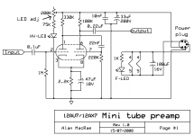
Actually there is a chance to have poor low frequency response because the capacitor at the output is just 20 nF.
It should be minimum 10 x bigger (220 nF...470 nF).
Last edited:
hi there
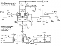
Big OOPS here, wrong schematic, new one attached (its from the same person that designed the first one, he made a few changes).
about wiring: short as possible (<1m shielded)
how i finded out? bypassing the preamp there is a lot of treble being played thru it: almost none.
tubes are matsushita.
Big OOPS here, wrong schematic, new one attached (its from the same person that designed the first one, he made a few changes).
about wiring: short as possible (<1m shielded)
how i finded out? bypassing the preamp there is a lot of treble being played thru it: almost none.
tubes are matsushita.
Attachments
I assume this is some sort of guitar preamp/FX box? That would explain why the designer believes that any twin triodes with the right pinout can substitute for each other.
Does the amp you are driving have an input RF filter? If so, its capacitance combined with the fairly high output impedance of this preamp will reduce treble.
Does the amp you are driving have an input RF filter? If so, its capacitance combined with the fairly high output impedance of this preamp will reduce treble.
According to the circuit diagram, the high frequency response should exceed 100 kHz.
Edit: what is the output impedance the device where you take the audio signal to this amplifier ?
good question, is a Realtek codec based onboard audio, I have no idea of the impedance of it
Last edited:
")
- Status
- This old topic is closed. If you want to reopen this topic, contact a moderator using the "Report Post" button.
- Home
- Amplifiers
- Tubes / Valves
- 12au7 valve preamp (again?)