Yes. It is a combination on both transformer and the R1 replacement. May be the two transformer ratio differ from one other also.
At B+ = 265V (inductor output) and if Vbias, remain at -35V, your tubes are running too hot. It won't live long as is. To put it back to within spec, you need to either #1, increase your bias to -45V or #2, reduce B+ to 225V and keep bias at -35V.
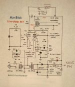
I would consider making R1 to (265-225)/((2*35ma)+front end). Let say each front end triode take 2ma, 40V/74ma = 540 ohms. You can use the inductor + new cap to feed Vplate to the front end triode.
At B+ = 265V (inductor output) and if Vbias, remain at -35V, your tubes are running too hot. It won't live long as is. To put it back to within spec, you need to either #1, increase your bias to -45V or #2, reduce B+ to 225V and keep bias at -35V.
I would consider making R1 to (265-225)/((2*35ma)+front end). Let say each front end triode take 2ma, 40V/74ma = 540 ohms. You can use the inductor + new cap to feed Vplate to the front end triode.
I agree with Alllensoncanon that the combination of the higher PS transformer and the slightly lower impedance of the choke vs the resistor (for R1) is where the increased B+ on the plate is probably coming from (as well as your mains if it runs a little high). I don't have Fred's schematic in front of me but I would probably suggest NOT putting the choke in series with a resistor to drop the voltage. I don't fully follow Alllensoncanon's suggestion of the choke + new cap to feed the plate of the driver triode but perhaps s/he can explain further. It might work.
If you use a resistor you might consider preceding or following the PS diodes with a resistor (e.g. prior to the first cap). An even better arrangement might be to use a CL90 "inrush limiter" at one output of the transformer (the one tied to the diodes). These have high resistance when cold (so they limit current when cold) but then drop quite a lot as they warm up. The CL90 seems to have 120 ohms when cold and as low as 4ohms when hot. The high startup resistance reduces startup ("inrush") currents. The limiters are designed to reduce resistance as they warm up so they eventually get out of the way of the PS (and don't waste a ton of power once they reach steady state).
The CL90 is designed for a max steady state current of something like 2A (by which time it will have dropped to 4 ohms). It still burns a few volts even at the low resistance. Since you are looking at less than 100mA of operating current, the CL90 won't likely drop to 4 ohms so you'll have more than a few volts dropped by it. I don't know how much voltage to expect them to drop, but they are cheap enough you could try it. If you do, please report back on how they worked.
And here's a trick. If it drops too much voltage after warmup because it never warms up enough, you can wrap it in heat shrink (or even wrap it in wool and heat shrink) to increase it's temperature while operating. That will, of course, drop the resistance, which increases the voltage put out by the PS. Again, that's if using the CL90 drops too much voltage.
I repeat I haven't tried this but they are designed to be used in this way and in theory it should work. Do some reading up on inrush current limiters so you understand how to use them.
Thanks both for your input. Please remember that I'm really new to this and much of what you advise requires a lot of boning up by me.
I'm kinda of the opinion, knowing little, that if the amp works as is, albeit chancing a shorter tube life, I'm loathe to experiment further until I really understand what it's about.
If it's any help the bias voltage is -27v with the tube in or out. Fred said -35v
Does that make any sense? Should there be a difference-tube in/out?
Did you measure that -27V at the output of D4 and C5 -? Or was it from pin 1 of the 6EM7? Reading bias voltage from C5- is more reliable unless you have a high impedance volt meter. I suspect you have some measurement error on the -27V reading. That bias voltage plus 265V plate likely will draw too much current from Cathode (pin3) to plate ( pin2) and destroy the 6EM7 tube.
I would suggest replacing the inductor with a resistor for now. Once you get the bias voltages to where they needs to be. Add the Inductor (plus a new cap, say 100uf 450V) to filter the preamp triode plate voltage (pin 5)
I would suggest replacing the inductor with a resistor for now. Once you get the bias voltages to where they needs to be. Add the Inductor (plus a new cap, say 100uf 450V) to filter the preamp triode plate voltage (pin 5)
I agree if your bias really IS -27v at C5 then with the high B+ you're starting to burn a lot of power in the tube and tube life may be affected. I'm not sure what your output triode current is under the current build but assuming it's 35mA in the output triode, you're burning pretty close to the max dissipation limit for the tube.
But more importantly, can you check the values of your heater voltage and components in the bias circuit, as well as measuring at C5 as Alllensoncanon suggested? I don't understand why you'd have -27v.
For the B+ I like Alllensoncanon's approach. I'm also quite curious if the CL90 would do the trick keeping the choke in it's current place. So you know, the CL90 would go at the output of T2 just before the two diodes. Since a CL90 is maybe $2-3 US, it seems like an easy quick test to make. But your hesitation to try something before you know more is a good instinct in this hobby.
Good luck and keep posting.
With a 7ohm dummy load on the output, the tube in and power on I got -27v at pin 1 ( Fred said at least -30v.
I'm wondering, and Fred wouldn't have tested this, if using 240v with a bridge and the other changes required on the PS, if this alters the parameters of the whole thing.
Fred made this amp available for us with a 240v supply by an addendum in Part 4, which of course is what I followed. You guys on the other side of the ditch wouldn't have much to do with 240v, ( except using a variac perhaps if the need ever arose) so, maybe there is some difference in the operating parameters.
I'll build the other amp the same as the first, see if I'm happy, and then very likely delve in. I'm very much obliged for the comments...everything I read from guys who know far more than I adds to my knowledge, so by all means please feel free..
So you know, the CL90 would go at the output of T2 just before the two diodes.
That's fine, I've looked into the CL90 and now I know basically how it works and the reason why you would use such a thing. What I'm not so sure about is how to wire it in. Do I wire it across the AC terminals on my bridge ( I'm not using the two diode setup). Or does it go in by interrupting one line to AC. (in series?)
Allensoncanon has suggested a 510ohm 5w for R1 in place of the 100ohm. Does this mean ditching the choke? It can't go in series with the choke surely? Otherwise there would be a too-big voltage drop for B+.
Last edited:
Alllensoncanon suggested removing the choke and replacing it with a 510R resistor instead of the 100R resistor that Fred called for. Take the choke out and put it into the driver circuit AFTER the connection with the output transformers on the power triode section.
I have to think about how best to wire the CL90 since you aren't using the diodes as specified by Fred. Maybe you'd need 2, one for each side of the transformer? Not sure when I'll get a chance to think about it but I'll get back when I do.
I have to think about how best to wire the CL90 since you aren't using the diodes as specified by Fred. Maybe you'd need 2, one for each side of the transformer? Not sure when I'll get a chance to think about it but I'll get back when I do.
If I'm using 240v (or thereabouts) I would expect to see 336v at the output of the bridge (would the 100ohm resister bring it down further before B+?)
I'm actually seeing 338v at the plate (no tube) so that would seem to confirm the above, except it should be less having gone through R1. (should I also expect some losses through the OPT before the voltage arrives at the plate?)
With the tube in I'm seeing 265v at the plate..
Make any sense?
I'm actually seeing 338v at the plate (no tube) so that would seem to confirm the above, except it should be less having gone through R1. (should I also expect some losses through the OPT before the voltage arrives at the plate?)
With the tube in I'm seeing 265v at the plate..
Make any sense?
Without the tube inserted, there is no current, thus no drop in B+ voltage. You see pretty much what's coming out of the transformer at the tube pin. But add the tube and it draws current. If it draws 35mA +/- that would mean a drop over the 100R resistor of 3.5v (Ohm's law V=I * R, or V=0.035 * 100). But it would also have to go through the diodes with their voltage drop and the output transformers.
Adding a resistor in line with the choke in the PS would indeed drop more voltage. But there may be unintended consequences of doing that. It's just not something I know anything about. But you could try it if you don't mind possibly absorbing some parts costs...
I do like Alllensoncanon's suggestion to go back to simple, remove the PS choke and replace with a 510R resistor at R1 and focus first on achieving the stated operating point. Once you've succeeded there, THEN you can start to substitute. Unless you know enough design concepts, I'd stay away from diverging from the design until you're succeeded on that front. Once you have that down, then you can vary the design elements to your heart's content. And if you do it carefully you'll learn a ton!!!
I do like Alllensoncanon's suggestion to go back to simple, remove the PS choke and replace with a 510R resistor at R1 and focus first on achieving the stated operating point. Once you've succeeded there, THEN you can start to substitute. Unless you know enough design concepts, I'd stay away from diverging from the design until you're succeeded on that front. Once you have that down, then you can vary the design elements to your heart's content. And if you do it carefully you'll learn a ton!!!
Ok, thanks Carlp..
I substituted the choke for a resister R1 because of the suggestion that a choke would be quieter than a resistor.
Not knowing anything about chokes I went for one which would fit in the box and be at least 3H per the same suggestion. Before it was pointed out that the choke was 86ohms, a bit short of the 100 required, I assumed it was fine.
Allensoncanon suggests the 510R instead of the choke so I can certainly try that.
Your explanation above makes perfect sense, something I've now learned. I knew about Ohm's law from school 100 years ago but never had a need to use it. It's quite simple in your explanation, and it's how one derives required values, I can see that in your example.
Ok, well, the wife and I are on a cruise till after Xmas, during which time other parts will have arrived for me to complete the other amp, and we'll take it up from there.
Is the current draw of the 13EM7 (35mA) true, or a suggestion? Maybe I can find out by looking at the specs. Given that I have this figure I can calculate the voltage drop at B+ using a 510R.
We sail on Monday so no doubt I'll have other questions before then. Don't you just love this hobby...?
Try these changes.(Re. R1)
Thanks Allensoncanon,
Just curious about the need for a 5W for R1. I'm going to give it a try as you suggest, but 5W? Aren't they the noisy wire-wound types?
I like metal film for various reasons, but don't think I could get a 5W in metal film.
Any suggestions, particularly if I could go lower wattage...?
Just reading a guide on noise of various resistor types, and wire-wound have the lowest noise. (The Resistor Guide, your guide to the world of resistors)
This is for R1 510R 5W per Allensoncanon.
Who would have thought...?
This is for R1 510R 5W per Allensoncanon.
Who would have thought...?
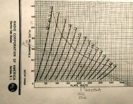
This load line chart may explain better. The curve line is the 10W specified plate dissipation of the 6EM7. Anything on the lower left of this curve is within spec. Line A is Fred N's design intention. Line B is what changing R1 to 510 ohms should get you to. I think it is a good alternative given the parts you installed at hand. Also I suspect that your bias is not -27V but closer to -40V instead. The high impedance of the grid input is giving your voltmeter reading error. Line C is what I suspect you are at now. It should sound fine if you don't mind tube longevity and keep an eye on it. It has a 15W plate dissipation.
What is the voltage on the negative side of C5 connected to D4 and R4. That should be closer to your real bias.
What is the voltage on the negative side of C5 connected to D4 and R4. That should be closer to your real bias.
Attachments
According to what I can find out, the current draw of the 13EM7 is 0.045mA +/-
So with a 510R for R1 gives a 23v voltage drop for B+ (0.045x510)=22.95v
I assume Allenscanon chose 510R deliberately to drop B+ a significant amount.
This being so, it would appear that this value for R1 will give the tube an easier life at the expense of a small decrease in output watts. Since I've only got around 1W to play with on the 13EM7 I can hardly afford it, but I don't want the tube lasting a short time before giving up the ghost. Perhaps it will be worth it.
A cheap 510R 5W resistor is all it takes to find out...
- Status
- This old topic is closed. If you want to reopen this topic, contact a moderator using the "Report Post" button.
- Home
- Amplifiers
- Tubes / Valves
- Fred Nachbaur SET amp: input capacitor