Have anyone any experience building TENA, any good reason till that I shouldn't?
http://www.normankoren.com/Audio/TENA.html
/Magnus
http://www.normankoren.com/Audio/TENA.html
/Magnus
")
Nice Amp
I like the design; I do not believe that toroidal output transformer is required. It true they have more bandwidth and there also can pass more noise and most tube amps do not use them.
I like the regulation and the bias designs. However, I am not the fond of his use of local feedback on the front gain stages. In addition, his layout is a little crude. All in all it an ok design, but there are a lot of nice tube design around
But you are probebly right, I shouldn't built it when I lack experience building tube amps
That is not what I meant...I meant that you should rather build something simpler ....I have built a couple of amps before...but that schematic looks very daunting to me...with all the bias circuits and regulators....etc, etc. even the main amp itself is complex as far as I am concerned...
Cheers,
Bas
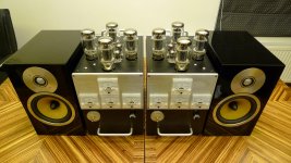
TENA 3
I built a variant of TENA - the reduced feedback version.
I did my own layout for the components. I also changed the input stage to be fully balanced and used locally sourced toroidal output transformers which limit the frequency response to 27kHz. I also used KT88s.
This was my first tube amp build. It sounds good to me.
Some lessons learned:
12AU7s work OK (and look pretty) but 6SN7s are more linear and result in lower distortion so stick with 6SN7s. I'm now using a 6SN7 in an adapter for TU3 and TU4 and using 12AU7s for the others. This combination is OK.
I think electrolytics CBX1, 2 and 3 and CB5 should have the positive side connected to ground (the bias voltage on the other side is negative).
I used 6.8K for R3F.
The protective diodes mentioned in the text are essential. There are some for the MOSFETs and some protecting the bias servo op amp inputs. They are shown in the layout diagrams but not the circuit diagrams.
Attachments
- Status
- This old topic is closed. If you want to reopen this topic, contact a moderator using the "Report Post" button.
- Home
- Amplifiers
- Tubes / Valves
- The Emperor's New Amplifier