Out of curiosity, has anyone out there tried a hybrid partial feedback SE amplifier using one of the IXYS or Supertex depletion mode fets for the front end? Both a Schade-style feedback or an E-linear scheme would be possible. I'm already doing something similar (but all sand-state) in my "SiC Puppy" SE amplifier (see the Pass Labs section if you're curious), and it sounds pretty nice. I'm definitely going to try it some time, but I have projects stacked up to the moon right now, so I won't act on this idea until I finish at least a few of the "works in process".
In one of the sound practices issues (1994), J.C. Morrison had a design (Dinosaur) with a 2SK30 fet at the front.
Why not use "SEARCH" before asking😉?
Michael Koster has done it the way it should be done! This one is seriously engineered without wasting components:
http://www.diyaudio.com/forums/tubes-valves/165221-most-linear-triode-strapped-pentode-7.html#post2204502
Michael Koster has done it the way it should be done! This one is seriously engineered without wasting components:
http://www.diyaudio.com/forums/tubes-valves/165221-most-linear-triode-strapped-pentode-7.html#post2204502
If you could dig up that schematic, I'd like to compare it with what I have in mind. This isn't the first tube/fet hybrid I've done. The "Shrine", my very first tube amp, married a triode- cascoded jfet with a ultralinear 1625 output stage. I have a few other sand/vacuum mutant hybrids still in the pipeline.
I haven't seen anyone marrying a naked depletion mode mosfet with a pentode in the classic "Schade" feedback scheme. I've seen jfet/tube hybids used for RIAA input stages before I ventured to do the "Shrine" amp. Given the age of the example you cite, I suspect that may be another example.
I haven't seen anyone marrying a naked depletion mode mosfet with a pentode in the classic "Schade" feedback scheme. I've seen jfet/tube hybids used for RIAA input stages before I ventured to do the "Shrine" amp. Given the age of the example you cite, I suspect that may be another example.
Revintage - you always have the snarky way of expressing yourself... The Koster circuit uses a mosfet in front, but it wasn't what I had in mind at all. I'll be doing a classic 2-stage Schade feedback circuit using something like a DN2540N5 for the front end (pentode in disguise) or one of the smallish IXYS 1000V depletion mode fets with the beam power pentode of my choice for the output. I may look at cascode vs. conventional front end to see what difference it makes. I really don't care if you think that wastes components or not, after all, they're mine to waste if I see fit.
The Koster circuit looks similar to what I've been simulating with a Zen variant I'll get around to building one of these days, except that mine's a class A push-pull (Revintage wouldn't like the component count). I may try his circuit with my "Shrine" amp (I've been musing about converting it to partial feedback for some time) to see the difference between the classic Schade scheme and his. I would still use the jfet cascoded with a triode I used in the original amp as input stage, as that's already in place. I'll try the classic Schade circuit first, as it's the least violent rearrangement of what I already have in place, and I don't have a lot of spare time. Right now the "Shrine" circuit uses a jfet cascoded with a triode at the input, driving an ultralinear-connected 1625 at the output. If I keep that lineup, I'll probably settle for the direct-to plate connection between the input stage load and the output, but keep the AC coupling between stages (it's more parts, but I'm not rebuilding the whole amp). If I want to go all the way, I'll build another amp.
Jaap - I'm still interested in seeing that 1994 circuit if you can lay hands on it.
Jaap - I'm still interested in seeing that 1994 circuit if you can lay hands on it.
Last edited:
No need to start personal disputes...🙁
I actually found the start of the thread very interesting.
Since wrenchone asked for a hybrid with depletion Mosfet and maybe Schade-style feedback, I don't see why Micheal Koster's circuit that revintage suggested does not fit the bill (low component count or not).
Could you (wrenchone) elaborate on why this is not what you had in mind?
I am still on the lower slope of the learning curve, so I always appreciate comments/discussions on a particular circuit - good way to learn.
There are often issues with a particular design, I just did not have on the radar.
Thanks for the effort.
Martin
I was looking for a simple classic two stage AC coupled amp, pentode input and output, partial feedback, with mosfet substituted at the input.
Koster's amp is an extreme stripped-down version of the same, omitting the AC coupling between stages and feeding completely back into the input stage from the output instead of partially. It took a second look to see that.
Two of the more conventional schemes as compared to Koster's are the "Schade" partial feedback circuit (named after its inventor, the father of the beam power pentode), which has a feedback resistor connected between the plate of the input stage and the plate of the output tube, and the "E-linear" scheme, which connects the plate load resistor of the input stage to an ultralinear tap on the output transformer primary instead of to B+. The Schade scheme was what I originally had in mind when I posted.
Koster's scheme moves that input plate load resistor right down to the output tube plate (the ultimate "E-linear") for even more feedback. If I had waded through an bunch of Schade posts/threads, I might have eventually found Koster's circuit, as it was buried 1/3 of the way into "the most linear triode" thread (a thread I stopped following far enough back I'd forgotten about it). The other innovation of Koster's circuit is the direct coupling between input and output stages.
As usual with DC coupled circuits, it has some compromises. I don't necessarily like blowing 70V across a cathode feedback resistor. The cathode is elevated at 70V above ground as well, which is getting a bit close to the usual 100V cathode to filament voltage limit. In the usual tube amp, it's possible to elevate the filament a bit with a bias network to reduce the heather to cathode potential, so that can be worked around if you accept the cathode resistor voltage drop. The advantage of using the mosfet at the input with Koster's scheme is that it can operate quite comfortably at 30V drain voltage and still have plenty of room for signal swing. This limits the amount of extra voltage dumped on to the cathode resistor of the output stage in addition to what already needs to be there to properly bias the output tube. The mosfet looks pretty much like a pentode in overall V-I characteristics, so it lends itself well to a Schade/E-linear-style feedback scheme, partial or full-tilt. You could potentially try the same thing with a pentode front end, but with a pentode, you would need to run the plate at a much higher potential to prevent it from running out of gas, meaning that you'd have a even higher potential across the cathode bias resistor of the output stage (more voltage/power burned). It may be possible to "starve" a pentode to allow it to run at lower plate voltage, but this would most likely eat most of the gain/transconductace that makes this feedback scheme so attractive. Compromising and using AC coupling between stages would allow you to do a similar scheme, at the cost of a coupling cap and another resistor.
The one big difference between the mosfet and the pentode is that the mosfet is more directly affected by Miller capacitance between gate and drain, not having the shielding effect of the pentode's screen grid. Cascoding the mosfet would help fix that, and might be worth a try - the input would be a bit easier to drive. It might also have better THD at high frequency - remains to be seen.
There are elements of Koster's circuit I might end up using, DC coupled or not. A "hey, other people are trying this, look at this link", would have worked just as well as the "direct" approach.
As I mentioned previously, I'll probably try an intermediate version on an amp I already have built up. I have about 8-9 amps in various stages of construction, so I want to limit involvement just now so I can finish a few things. I want to keep the input stage I already have to avoid completely tearing the amp apart. It uses a jfet/triode cascode on the input stage, which needs some voltage at the triode plate to work properly. The guts are all inside a 6" cube with tubes on top, so DC coupling and an extra 10W or more dissipation inside would not be appreciated. The amp uses a custom SMPS that also fits inside the cube - I don't want to rewind the transformer to make up for the extra voltage drop across the cathode resistor. This means, I'll try the Koster feedback scheme with AC coupling. Not as simple as some would like, but as simple as I'm going to make it for right now.
Thanks wrenchone, for going step by step through the mentioned circuit and the one you have in mind and mentioning the problems.
I had noticed the problem of limited voltage swing if the Mosfet would be replaced by a Pentode but did not see the problem of the 70V burned in the cathode resistor (and the cathode to filament voltage limit), which might be a problem in some cases.
Thanks again for the detailed explanation.
Martin
You could linearize the V to I of the input FET plus the output tube all together if the Schade feedback resistor were taken back to the Fet source terminal. The higher feedback R atten. ratio looks like it will help with the DC levels too. Someone had an all tube SE version like that I've seen here, don't know if a Fet/Mosfet version has been done. E-linear seems to invite phase problems, a top quality OT may be required.
Last edited:
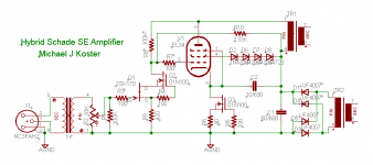
Here's how that design evolved. I'm building a pair of these into my Klipsch LaScalas.
The cathode voltage here is about 50V out of total 500V B+; not too wasteful for my purposes at only 3 Watts extra dissipation, no big deal really.
I don't see how this is NOT a "Schade" scheme. R8 is a feedback resistor from output plate to the input plate (drain).
"Partial" feedback?
I have added a second resistor to increase the idle current on the front cascode, but NB this has only a small effect on the feedback ratio, in this case reducing the feedback by only a few percent. Why? Because the FB resistor is bring swung by the inverted plate signal and thus is responsible for most of the dynamic load on the driver.
The heater voltage is not a problem; can be floated if you're paranoid since there's only one heater.
With AC coupling you would just need to adjust the value of the "static" load resistor to achieve the desired idle current in the driver since there will be no DC current in the feedback resistor.
I'm quite happy with this approach and it sounds great!
Cheers,
Michael
PS Another goodie in this circuit is that practically all the PS ripple is passively isolated from the signal by the MOSFET dynamic drain resistance. The output is nice and quiet even with volts of PS ripple.
Attachments
Last edited:
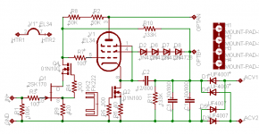
I guess it depends on what one is trying to optimize. The beauty of this is it's so simple it can be built on a single terminal strip or simple PCB
Attachments

Last edited:
It may be useful in the case of a somewhat challenged output transformer to save a little gain and feed it back to the source from the output as smoking-amp suggested. It won't rescue a totally pathetic transformer, but it can help a transformer that''s a little challenged in the bass department.
It would be very interesting to try this scheme or some other partial feedback approach with a 6HS5/6HV5A beam triode. They have a lot of gain/transconductance, but sucky plate resistance. Feed that gain back and make a real triode out of the tube! It will probably take some grid current to get the tube to operate well at less than electric chair-magnitude, but given the specs, it probably wouldn't take very much. A little source follower plopped between input and output stages would give one total assurance of handling just about any grid current required, at the cost of some extra complexity.
It would be very interesting to try this scheme or some other partial feedback approach with a 6HS5/6HV5A beam triode. They have a lot of gain/transconductance, but sucky plate resistance. Feed that gain back and make a real triode out of the tube! It will probably take some grid current to get the tube to operate well at less than electric chair-magnitude, but given the specs, it probably wouldn't take very much. A little source follower plopped between input and output stages would give one total assurance of handling just about any grid current required, at the cost of some extra complexity.
Last edited:
Michael, regarding the Schade/not Schade matter, it took a second look at your circuit to see what the circuit was really about, as I was a little steamed by the "direct" approach. I prefer to see it as an "E-linear' taken to the extreme by tapping the feedback all the way down to the plate, but I suppose you could also look at it as a classic Schade feedback scheme with the B+ connected plate resistor on the input tube ratcheted up to infinity - works either way. More food for thought in any case, and it may affect some designs I have in the pipeline. The amp where I'm thinking of trying this approach has only 350V B+, and an input stage that needs some voltage to work properly, so I'll opt for AC coupling for my first try. I'll probably save some gain to feed back from the output, as I'm using mid-grade Edcor transformers (the GXSE series), which are the largest I can fit inside the 6" cubical case. The output is currently uses a classic SE ultralinear circuit (it was my first tube amp, inspired by the challenge of getting the works to fit inside a standard 6" cubical Hammond case ).
How well is the series zener screen bias scheme working for you?
How well is the series zener screen bias scheme working for you?
...
How well is the series zener screen bias scheme working for you?
This scheme is great for this circuit because the screen voltage as well as the grid, cathode, and plate all float on the power supply ripple. Thus there is no ripple voltage or current anywhere in the signal. It's a critical part of the PS isolation in this circuit.
Consistent cathode-screen voltage is maintained by virtue of the cathode CCS allowing the cathode to find the correct voltage as the B+ drifts, etc.
It will be interesting to see your results.
Cheers,
Michael
Michael: New or Old Circuit
Michael
I was about to build your 5881WXT "schadeode" circuit from last year when the new EL34 with cascode frontend appeared! Is the new circuit better than the old or are we talking about minor differences?
Michael
I was about to build your 5881WXT "schadeode" circuit from last year when the new EL34 with cascode frontend appeared! Is the new circuit better than the old or are we talking about minor differences?
Michael -
I'm also curious about the evolution between the more extreme design("schadeode") linked by Revintage earlier in this thread and the one you show in the later posts here. The later design looks to a large extent what I would have done, except for the DC coupling. My comments about "not looking like conventional Schade" were addressed solely regarding the first circuit, and then, only until I got a second look.
It would be interesting to try one of theses schemes with a beam triode. I also have in mind a couple of gross sweep tubes, as I have a pair of Quicksilver SE transformers that are looking for something powerful and unusual to drive them.
I was planning to mod my "Shrine" amp anyway with some sort of partial feedback scheme before I started this thread, as I wanted to eke out a little bit more power than what can be squeezed from the 1625s in straight ultralinear mode. I have two options available:
1) Ditch the hybrid front end and do classic partial feedback amp with a 7-pin pentode like the 6AH6 or 6EW6.
2) Keep the hybrid front end and use either Schade or E-linear partial feedback(the transformer does have an ultralinear tap).
An all-semiconductor front end is not in the cards for the Shrine amp, as I'd have to replace the whole top deck. What I will do if I choose 2) is replace the PN4393 jfets I'm currently using in the front end (short channel) with 2SK117s (longer channel, higher output impedance, more transconductance for the chosen drain current). It's an opportunity to use these devices (I bought 200 recently), and I 'm resisting the expedient of going all "big gun" and tossing in a 2SK170. Once this is done, it's a fairly simple matter to gin up the partial feedback. I was thinking of biasing the output screens by slinging a resistor between B+ and the input load resistor with a bypass cap and running both the output screen and input stage off this lower voltage. The down side of this would be modulation of this voltage if the screens start to draw heavily.
It would be very interesting to try this scheme or some other partial feedback approach with a 6HS5/6HV5A beam triode. They have a lot of gain/transconductance, but sucky plate resistance. Feed that gain back and make a real triode out of the tube!
But wouldn't the open loop gain actually be low with a practical transformer, limiting the feedback?
I would run the beam triode at a less life-threatening plate voltage, say 600-700V. The tube would then require A2 operation for useful output, but I suspect not a whole lot of drive current would be needed. I have some Transcendar 8k SE transformers that could be used to breadboard something when I have the time. I also suspect the huge mu and transconductance shown in the data sheets are obtained at high pulsed current (the tubes were after all intended for use in a pulsed shunt regulator), so a reasonable DC plate current more in line with the plate dissipation ratings will yield mu and gm values that are still very high, but not in the "instant oscillator" regime. This is actually a relief of sorts because a tube that frisky would be hard to tame.
There's been some talk about the beam triodes in various threads, but not too many people have actually followed through and built something. Those that have don't have a whole lot of documentation for their efforts, except for one thread here that looked at using the 6HV5A to drive an 845. I'd like to settle the question for myself, as I have a reasonably large box of 6HV5As that has been gathering dust. I have to admit, though, that there's lot of low-hanging fruit in other places, so I haven't been really motivated to open that box just yet and get cracking.
There's been some talk about the beam triodes in various threads, but not too many people have actually followed through and built something. Those that have don't have a whole lot of documentation for their efforts, except for one thread here that looked at using the 6HV5A to drive an 845. I'd like to settle the question for myself, as I have a reasonably large box of 6HV5As that has been gathering dust. I have to admit, though, that there's lot of low-hanging fruit in other places, so I haven't been really motivated to open that box just yet and get cracking.
- Status
- Not open for further replies.
- Home
- Amplifiers
- Tubes / Valves
- Hybrid Partial Feedback SE Amplifier