Hi Fran,
I had another look at the datasheets for the 6N1P (under frank.pocnet.net). If you have a real Soviet 6N1P, it looks like the cathode can be up to 100V more negative than the heater, and up to 250V more positive than the heater.
Since we have the first cathode basically at the same potential than the heater (heater should be somewhere between +/. 6.3V with regard to ground), and the cathode of the Concertina roughly 80V more positive than the heater, there should be a large safety margin, and you should be fine with not elevating the heater, I think.
The datasheet for the Svetlana 6N1P looks to be a bit tighter ... mentioning +/- 100V peak, which could be close with signal swing.
Regards, Claas
Yes, a 10k plate-plate primary OPT would work fine. Compared to an 8k p-p, the output tubes will operate in class A at higher signal levels (more horizontal load line), so expect slightly lower power out but also slightly lower THD. Also slightly better damping factor. Since the EL84s are triode-wired, load impedance is not super-critical (there's a fairly broad area of reasonable operation).
Personally, I like the idea of using a higher impedance primary load on the output triodes. Less power, true, but cleaner.
Personally, I like the idea of using a higher impedance primary load on the output triodes. Less power, true, but cleaner.
@analogadikt - if you build it, post a few pics here. I still have mine and enjoy it a lot.
Well, I recently pulled this amp off the shelf to have a listen to it after using some SS amps for a while. I was surprised again at how good it sounded, so I had a bright idea to use my new distortion measuring rig to see what it looked like. This turned out to be a mistake, when I hooked it up and took a look at the spectrum, it wasn't terrible, but also wasn't great. Distortion at 1W in 8R was 0.4% and noise wasn't brilliant either at -50something dB down. A fair chunk of that noise was from 50hz and its harmonics, and also from some sidebands around the 1kHz pilot tone. These looked really odd, spaced perfectly 100Hz either side of the fundamental, and I could see it mirrored on the 2nd and 3rd harmonics.
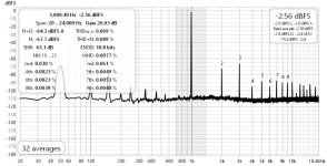
So I got to reading around a little in between other jobs, and saw a post here saying that 100Hz side bands either side of the fundamental could be related to AC heaters (I think it was @6A3sUMMER) . I had some DC supplies, so I got to thinking about fitting these, and wondering if I could do any better on the B+ I had a built Maida HV module I reckoned I could press into service. Anyway, I got time today to open it up and fit the modules, doing some other tidying up in the amp while I was at it (not that you'd know if you saw it). Anyway, the end of this story is that this had a very positive effect on the noise and also THD. Noise is now down to -67dB, and THD is down a lot to 0.069% on the channel shown. The second channel is a bit higher at 0.11% (all 1W into an 8R "real life" load). You will see that the harmonic profile is more 3rd than 2nd, about twice as much, even if low enough overall.
I used a simple LM317 CCS on the tail of the 2 EL84s, with a balancing pot. I know that I can minimise distortion in total by adjusting that balancing pot but it doesn't much change the ratio of 2nd to 3rd.
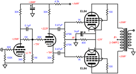
My B+ is a bit lower than Broskies original, 300V or so, with the front end about 40V less as per his schematic. I don't want more distortion, but I am curious as to how it would sound if the ratio of 2nd to 3rd were reversed. I've added his schematic here again for ease of reference. In my build I have DC heaters, Maida reg for B+ with an added RC stage for the front end B+, I have a red LED in the cathode of the input 6n1p and the LM317 ccs in the tail of the EL84 instead of the cathode resistor/cap. Also, I have mine wired as ultralinear rather than triode mode as his sch shows.
As it stands it sounds very good indeed, so this is really just looking to add a little spit and polish.
So I got to reading around a little in between other jobs, and saw a post here saying that 100Hz side bands either side of the fundamental could be related to AC heaters (I think it was @6A3sUMMER) . I had some DC supplies, so I got to thinking about fitting these, and wondering if I could do any better on the B+ I had a built Maida HV module I reckoned I could press into service. Anyway, I got time today to open it up and fit the modules, doing some other tidying up in the amp while I was at it (not that you'd know if you saw it). Anyway, the end of this story is that this had a very positive effect on the noise and also THD. Noise is now down to -67dB, and THD is down a lot to 0.069% on the channel shown. The second channel is a bit higher at 0.11% (all 1W into an 8R "real life" load). You will see that the harmonic profile is more 3rd than 2nd, about twice as much, even if low enough overall.
I used a simple LM317 CCS on the tail of the 2 EL84s, with a balancing pot. I know that I can minimise distortion in total by adjusting that balancing pot but it doesn't much change the ratio of 2nd to 3rd.
My B+ is a bit lower than Broskies original, 300V or so, with the front end about 40V less as per his schematic. I don't want more distortion, but I am curious as to how it would sound if the ratio of 2nd to 3rd were reversed. I've added his schematic here again for ease of reference. In my build I have DC heaters, Maida reg for B+ with an added RC stage for the front end B+, I have a red LED in the cathode of the input 6n1p and the LM317 ccs in the tail of the EL84 instead of the cathode resistor/cap. Also, I have mine wired as ultralinear rather than triode mode as his sch shows.
As it stands it sounds very good indeed, so this is really just looking to add a little spit and polish.
Attachments
Ah @poseidonsvoice - I didn't take screen shots. I know I should have, but didn't.
Third harmonic dominates because second should optimally cancel out.
And yes, EL84 in triode PP into some 10k load does sound really nice.
Unless your load is something less than 10k and because you use less than 340V you may want to try out with a reduced Rk (to run the tubes with higher Pa, 14W max !), most likely it will sound even nicer, (mine does, 11.2k loadimpedance)
Last edited:
Generally speaking, push-pull output stages, when properly implemented, will generate more 3rd harmonic distortion than 2nd harmonic. In this PP EL84 amp's circuit topology, the majority of the 3rd harmonic distortion will come from the output stage, as being push-pull it will cancel out 2nd harmonic,
The THD of a small tube amp like this is almost always going to be higher than that of a modern solid state design. The question then is, is the THD from this tube amp low enough?
If you're really getting THD at 1W into 8 ohms of 0.09% (the avg of 0.069 and 0.11) then I think you've done alright.
When I simulated that circuit in LTspice, I got THD for 1kHz input with 1W output of 0.34%, with an OPT having 7.6k ohm primary impedance (plate-to-plate).
Now that you've cleaned up the power supplies, you might want to experiment with adding some global NFB, to see if you prefer the sound with lower THD. You could measure your results and then listen, compare, see what you like best.
But seriously, how's it sound?
PS - If you look at the couple of tube amp reviews w/ measurements at Audio Science Review, you'll see that yours is comparable to very expensive commercially made tube amps.
Bob Latino modded Dyna Stereo 70 measurements (with NFB applied):
Last edited:
Thanks for the schematic. I may implement that front end. My Leak Stereo 20 has been converted to use 8x 6S4 triode tubes in PPP. Solid state rectification and a choke in the B+ supply. I ran out of 6.3V current so used the 5V supply to feed the input tubes which are lower voltage types like 4BQ7 and 5BK7.
My mention of DC powered filaments, versus AC powered filaments was most often aimed at using DHT, Directly Heated Triodes.
An EL84 has a filament and a cathode.
If AC filaments causes hum from an EL84, the most likely cause is a faulty EL84 that has high filament to cathode leakage current.
The other hum with AC powered filaments that relates to filament to cathode leakage is the concertina phase splitter, the cathode is un-bypassed, any leakage current from the filament to the cathode causes hum (find a less leaky tube in that circuit, select if necessary.
Even if you use DC power for the filament, you still have a problem . . . the plate load resistor is supposed to be equal to the cathode load resistor.
But what is the resistance of the cathode load resistor that is also in parallel with the leaky filament to cathode resistance . . . the phase splitter outputs will have different signal voltage outputs, resulting in less 2nd harmonic distortion reduction of the amplifier.
Any AC powered filament tube, with an un-bypassed cathode that has filament to cathode leakage will exhibit hum if the leakage is large enough.
My mention of DC powered filaments, versus AC powered filaments was most often aimed at using DHT, Directly Heated Triodes
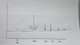
Ok, I hope I haven't mislead anyone or misconstrued what you said. Just when I read it after searching around I thought maybe that could be my issue. Note that it wasn't hum that was my issue so much as THD peaks either side of the fundamental. I'm regretting not taking a screenshot of the before amp tbh. What I've done to (badly) compensate for this is (poorly) draw what it looked like.
Moving on from that, I understand the 2nd harmonic cancellation now having read some more - being able to measure things opens lots of questions! The 6p14p used here are not matched. It is very interesting to see THD go up or down depending on adjustment of the balancing pot before the CCS.
The amp sounds excellent, bass is not as tight and controlled as say good SS amps, but really very good overall. I would totally recommend it.
I'll dig out the info on the output transformers. With the CCS I have there in the cathodes, I have 80mA (very close to 40mA per tube) and about 9-10V cathode to gnd. Current is on target but voltage there is lower than target in the schematic.
Attachments
The output transformers are 8K UL, large units built in Hungary. I bought them here in 2021.
https://www.diyaudio.com/community/threads/el84-pp-output-power-transformers.368303/
https://www.diyaudio.com/community/threads/el84-pp-output-power-transformers.368303/
I wish I could easily read through 216 posts in this thread.
But if you have 50Hz power mains, and full wave rectification, you have 100Hz ripple.
The choke also has 100Hz ripple, is it near to the output transformers?
Are you using a Magnetic Steel Chassis.
Either of those will impress 100Hz on the output transformer.
But because it is on the 1k, 2k, and 3k test tone and harmonics, it sounds like it is intermodulation.
A ground loop might do that (but then you would also have 100Hz hum at the low frequency end; not just the 100Hz sidebands on the test tone and test tone harmonics.
The push pull output should cancel most of the 100Hz ripple of the output transformers B+ at the center tap.
But B+ ripple at the concertina, and at the input stage is not cancelled.
From your schematic in Post # 206, I wonder about the filament to cathode leakage of the input and concertina triodes.
You are using a CCS in the cathodes, and a balance pot.
Is there a capacitor bypassing the CCS to ground?
A complete and accurate schematic is worth 1000 words, and at least 100 Posts.
Please . . . post an updated schematic.
Hum, and hum intermodulation products are such difficult things to find and pound down.
Last edited:
@6A3sUMMER - thanks for the post, it is always useful to read what you post.
So just to be clear - I no longer have those peaks/intermodulation either side of 1kHz in the hand drawn example above - some combination of moving to DC heaters and Maida reg solved that. I posted that drawing because another poster asked for it above.
I do not have a capacitor bypassing the CCS to ground.
I do have a tiny bit of hum in the amp, but not with shorted inputs, so I think what is going on is some AC mains hum. This is at a level where you don't notice it from the chair, but up close to the speaker you can hear it. I think it is AC mains hum because when I put a 10r in the input ground to star ground, it gets worse.
But other than chasing down that last piece of hum the amp is performing very well. I was looking at the H3 vs H2 but now understand the cancellation of H2 because the amp is PP.
woodturner-fran,
*** My latest balanced amplifiers with 1 Watt output, have 2nd harmonic and 3rd harmonic distortions almost equal, at about -50dBc (or better), 0.316% or less, for each the 2nd and the 3rd). With the rapid fall off of upper harmonics, the THD is 0.45% or better.
A dual triode is the input/driver stage; the push pull output stage is triode wired beam power tubes.
The only forms of negative feedback are: driver stage cathode-to-cathode, output stage cathode-to-cathode, and beam power tube output plate-to-screen (triode wired).
There is no global negative feedback.
The old rule that says Single Ended amplifier's 3rd harmonic distortion is 15dB less than the 2nd harmonic distortion, is broken when the driver stage 2nd harmonic distortion is nearly equal to the output stage 2nd harmonic distortion . . . that causes Serial stage 2nd harmonic distortion partial cancellation.
As you can see ***, push pull amplifier's 3rd harmonic distortion is not always larger than the 2nd stage harmonic distortion.
So just to close the loop on this (lol - for now anyway)
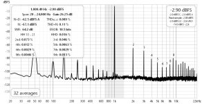
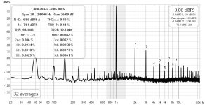
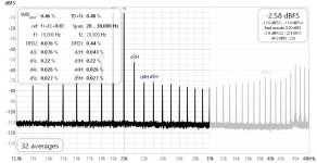
Attached are distortion measurements for each channel and also 19/20khz IMD as well. I'm pretty confident now of my THD measurements, but not so much with the IMD as I have little enough experience. Hopefully I am not incorrect in how I have done it. All measurements taken at 1W into 8R.
So this is Broskie's circuit as linked above, but with DC heater supplies, Maida HV reg for the B+, red LED in the cathode of the first tube, and 80mA LM317 in the tail of the EL84 cathodes. I have an adjustment pot on the cathodes, and using this I have tuned the distortion to give me just a hair more H2 than H3 - which actually means one EL84 runs a bit harder than the other but still well within spec.
The last thing I had to sort was a low level hum, which turned out to be interference between power and output transformers. Laying the power transformer in a different orientation completely cured that.
So I've been listening to it for the last few nights and I am pretty happy with it sonically. The amp is ugly as hell to look at, but once you don't look at it its fine") .
.
Attached are distortion measurements for each channel and also 19/20khz IMD as well. I'm pretty confident now of my THD measurements, but not so much with the IMD as I have little enough experience. Hopefully I am not incorrect in how I have done it. All measurements taken at 1W into 8R.
So this is Broskie's circuit as linked above, but with DC heater supplies, Maida HV reg for the B+, red LED in the cathode of the first tube, and 80mA LM317 in the tail of the EL84 cathodes. I have an adjustment pot on the cathodes, and using this I have tuned the distortion to give me just a hair more H2 than H3 - which actually means one EL84 runs a bit harder than the other but still well within spec.
The last thing I had to sort was a low level hum, which turned out to be interference between power and output transformers. Laying the power transformer in a different orientation completely cured that.
So I've been listening to it for the last few nights and I am pretty happy with it sonically. The amp is ugly as hell to look at, but once you don't look at it its fine
.Attachments
- Home
- Amplifiers
- Tubes / Valves
- Unexpectedly good EL84 amp