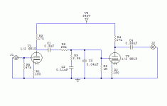
You might have a bit of a problem with gain, especially at the low end (common problem with passive). I haven't used that particular tube; what's the mu and plate resistance? Do you have any data on voltage noise density?
Also, a small resistor on the input of the first grid (say 1K if you're using MM) can be a phophylactic against RF.
Also, a small resistor on the input of the first grid (say 1K if you're using MM) can be a phophylactic against RF.
The output resistance of the first valve is a significant proportion of the series resistance in the RIAA network. To put it another way, equalisation accuracy will be critically dependent on ra.
You have a very heavy load on the first valve, so its gain will be significantly less than mu, and passive RIAA attenuates by a factor of ten. The signal presented to the second valve will probably be about double the output from the cartridge. Noise in the second valve will be very significant.
Sorry to £!$$ on your firework.
EC8010 said:The output resistance of the first valve is a significant proportion of the series resistance in the RIAA network. To put it another way, equalisation accuracy will be critically dependent on ra.
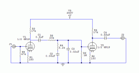
What do you mean by this? As in R3 and R8 in parallel represent the initial resistance value for the filter, and not R8 alone?
EC8010 said:You have a very heavy load on the first valve, so its gain will be significantly less than mu, and passive RIAA attenuates by a factor of ten. The signal presented to the second valve will probably be about double the output from the cartridge. Noise in the second valve will be very significant.
I tried squeezing as much mu as possible when doing the load lines while still staying within plate dissipitation limits. Wouldn't changing Ra just change the Ia for the most part as long as B+ is constant?
I want to get this going, so please help out further. I used this site for the filter section http://www.kabusa.com/riaa.htm . I havent found too much info on the actual theory behind the equalisation.
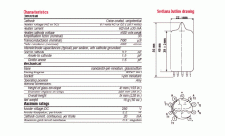
fdegrove said:6N1P is close to a 6DJ8 except for heater current according to Svetlana.
I think the 6N1P is a little beefier, no? Wa for 6N1P is 2.2W, while 6DJ8 is about 1.5W, from what I remember.
Hi,
Sure, I have no quibbles with your choice.
Rather that I disagree with many vendors marketing it as a direct equivalent of the 6DJ8 except for heater current.
The datasheet as given by Svetlana isn't even accurate if you compare it to other sources.
This is one of those tubes I'd put put on a plotter to find out more about it.
Hope that clarifies it,
I think the 6N1P is a little beefier, no? Wa for 6N1P is 2.2W, while 6DJ8 is about 1.5W, from what I remember.
Sure, I have no quibbles with your choice.
Rather that I disagree with many vendors marketing it as a direct equivalent of the 6DJ8 except for heater current.
The datasheet as given by Svetlana isn't even accurate if you compare it to other sources.
This is one of those tubes I'd put put on a plotter to find out more about it.
Hope that clarifies it,
Hi,
A few issues here:
- the passive RIAA correction as shown is loading down Rp heavily by your component choice.
- while doing the math on V1 you didn't take the load of the RIAA correction into account it seems.
- both halves of the tube are set up the same way, you have considerable insertion loss from the passive RIAA correction but V1 has the same high gain now...hence the gainscaling is wrong, hence the remark from other members about the possible ( real IMHO) noiseproblem from V2.
IOW, I'm not adding anything other than what EC8010 hasn't said already just expressing it in a different way.
Cheers,
What do you mean by this? As in R3 and R8 in parallel represent the initial resistance value for the filter, and not R8 alone?
A few issues here:
- the passive RIAA correction as shown is loading down Rp heavily by your component choice.
- while doing the math on V1 you didn't take the load of the RIAA correction into account it seems.
- both halves of the tube are set up the same way, you have considerable insertion loss from the passive RIAA correction but V1 has the same high gain now...hence the gainscaling is wrong, hence the remark from other members about the possible ( real IMHO) noiseproblem from V2.
IOW, I'm not adding anything other than what EC8010 hasn't said already just expressing it in a different way.
Cheers,
I'm sorry I guess I didn't express myself clearly. I didn't really understand what EC8010 meant, that's what I was wondering about. Should I take the resistance of the filter in parallel to the plate resistor of V1 to figure out the load? What should I do about the noise, grid stop resistors? Like I said I don't know much about RIAA equalisation, much else any equalisation. Thanks for the help.
I'm assuming that you are going to do this as a learning exercise, rather than in the expectation of producing a quiet phono stage.
The required values of your equalisation network (C2, C3, R9) are determined by the resistance it sees to ground. It sees R6 directly to ground, then R8 via C1 and ra//R3. There are sample variations between valves, so even if you have carefully determined ra for one valve at your operating point, another sample is likely to have a different value. Provided that ra is a small proportion of the total resistance that your equalisation network sees, its variation is not a problem. As a rough rule of thumb, R8 should be >10ra.
The required values of your equalisation network (C2, C3, R9) are determined by the resistance it sees to ground. It sees R6 directly to ground, then R8 via C1 and ra//R3. There are sample variations between valves, so even if you have carefully determined ra for one valve at your operating point, another sample is likely to have a different value. Provided that ra is a small proportion of the total resistance that your equalisation network sees, its variation is not a problem. As a rough rule of thumb, R8 should be >10ra.
EC8010, I see what you're saying with the resistance to ground, but how would I apply that to the page I used for the calculations (http://www.kabusa.com/riaa.htm)? Should I plug in Ra plus R8 for the value of the R1 of the filter on that page?
Not quite. The technique you are looking for here is "Thevenin". The value you need to substitute is the equivalent resistance seen to ground.
Start by working out the parallel combination of ra and R3, this is in series with R8, so add them together. This combination is in parallel with R6, so calculate this parallel combination and insert it into your equalisation calculations.
Start by working out the parallel combination of ra and R3, this is in series with R8, so add them together. This combination is in parallel with R6, so calculate this parallel combination and insert it into your equalisation calculations.
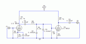
Alright, I think I understand now. Here is the revised version. Also, would there be any advantage to adding a resistor to ground between C1 and R8 in helping to achieve a lower AC Rp in front of R8? I don't think it would do much other than for more recalculation, but just thought I would make sure.
Attachments
Hi,
The fact that the first stage has it's amplification reduced considerably due to the RIAA network means that the second, that doesn't see this load and will now amplify the previous stages' noise + its' own noise at it's calculated mu will make for a noisy preamp.
This is called wrong gainscaling, we try to have to first stage amplify the most and lower gain from thereon onwards.
Especially if you intend to use a MM cartridge, a voltage device, this is important.
So, I didn't do any maths on your circuit but you should reduce the gain of the second stage.
Gain for a MM catridge may be too low which is often compensated for by the addition of a line stage where you target low amplification and low output impedance.
Another way to go about passive RIAA is to split the load and spread the correction over various stages, usually two, and apply the above again.
Designing a good preamp is often more complex than designing an amp.
Those are the places I'd certainly pay great attention to the PSU as well, PSSR and regulation of the B+ will often make a world of difference in this particular application.
Cheers,
Revised for less distortion, also why will having two identical gain stages add noise in the second stage? And can this be reduced with a grid stopper?
The fact that the first stage has it's amplification reduced considerably due to the RIAA network means that the second, that doesn't see this load and will now amplify the previous stages' noise + its' own noise at it's calculated mu will make for a noisy preamp.
This is called wrong gainscaling, we try to have to first stage amplify the most and lower gain from thereon onwards.
Especially if you intend to use a MM cartridge, a voltage device, this is important.
So, I didn't do any maths on your circuit but you should reduce the gain of the second stage.
Gain for a MM catridge may be too low which is often compensated for by the addition of a line stage where you target low amplification and low output impedance.
Another way to go about passive RIAA is to split the load and spread the correction over various stages, usually two, and apply the above again.
Designing a good preamp is often more complex than designing an amp.
Those are the places I'd certainly pay great attention to the PSU as well, PSSR and regulation of the B+ will often make a world of difference in this particular application.
Cheers,
Hi,
Certainly, the only thing that may happen is that absolute polarity of the input will end up reversed...
As long as you know which way the polarity ( I hate this term, much more prefer absolute phase) goes and take it into account, not a single technical problem stands in your way.
With the 6N1 you can share triodes' halves between channels when you ground the shield without fear for x-talk provided you space interchannel wiring and components far enough apart.
Cheers,
Could I lower the gain of the second tube and then add another low gain stage after that?
Certainly, the only thing that may happen is that absolute polarity of the input will end up reversed...
As long as you know which way the polarity ( I hate this term, much more prefer absolute phase) goes and take it into account, not a single technical problem stands in your way.
With the 6N1 you can share triodes' halves between channels when you ground the shield without fear for x-talk provided you space interchannel wiring and components far enough apart.
Cheers,
- Status
- This old topic is closed. If you want to reopen this topic, contact a moderator using the "Report Post" button.
- Home
- Amplifiers
- Tubes / Valves
- first attempt at phono preamp, will this work?


