Hi all,
I have a question:
If i have a stereo design, i.e a common power supply, and i want to configure a new PS, which is identical in design to the current one, but serves only on e channel, so i just cut current rating in half? the voltages don't change so, as far as i understand (and i'm a novice), the only thing that'll change is how much current is drawn by the circuit: only one channel instead of 2, hence half the current draw.
I'd love to be corrected if i am wrong or if i need to consider other issues before making such a move, i.e filter networks (RC's) etc.
Many thanks in advance.
Cheers,
Guy.
Guydot said:hence half the current draw.
In the simplest of senses yes... but it rarely hurts to have a bigger power supply...
dave
Oh and the amp is operating in Class A.
I also want to mention that i have no problem giving each PS the original current capabilities since i do not yet have the power transformers and they will be custom made by Bartolucci, so i have no problem spacifying whatever i want
Guy.
I also want to mention that i have no problem giving each PS the original current capabilities since i do not yet have the power transformers and they will be custom made by Bartolucci, so i have no problem spacifying whatever i want
Guy.
Hi,
Just EC8010s warped sense of humour?
Do you actually plan to build this amp as dual monoblocks or did you built the kit and want to transform it now?
If you intend to build from scratch from the diagram but as a pair of monoblocks I'd keep the xformer specs as is with the exception of the heater secondary.
There, I'd just specify halve the current rating.
The B+ will likely be a few volts higher but that can easily be fixed and by beefing up the PSU caps you'll end up with a nice pair of amps.
Cheers,
Why Whirled?
Just EC8010s warped sense of humour?
Do you actually plan to build this amp as dual monoblocks or did you built the kit and want to transform it now?
If you intend to build from scratch from the diagram but as a pair of monoblocks I'd keep the xformer specs as is with the exception of the heater secondary.
There, I'd just specify halve the current rating.
The B+ will likely be a few volts higher but that can easily be fixed and by beefing up the PSU caps you'll end up with a nice pair of amps.
Cheers,
Hi,
Thanks for your reply.
I do have this amp as a kit, but i'm doing a rebuild of the design incorporating several upgrades, the most dramatic (i hope ) of them are massive Bartolucci OPT's (10Hz-45Khz -3db point - not bad i recon ). Another change is putting voltage regulators on all HT lines and the KT88 bias in hope it'll be a worthy investment
I had a "fantasy" about transforming the input stage into a differential amp stage with an SE output so it can receive a balanced signal feed (i might have to connect it using pretty lengthy cables), but since i don't feel comfortable with the needed knowledge and experience there's a good chance i'll drop that ambition
Thanks again for all your replies.
Cheers,
Guy.
Thanks for your reply.
I do have this amp as a kit, but i'm doing a rebuild of the design incorporating several upgrades, the most dramatic (i hope
) of them are massive Bartolucci OPT's (10Hz-45Khz -3db point - not bad i recon ). Another change is putting voltage regulators on all HT lines and the KT88 bias in hope it'll be a worthy investment I had a "fantasy" about transforming the input stage into a differential amp stage with an SE output so it can receive a balanced signal feed (i might have to connect it using pretty lengthy cables), but since i don't feel comfortable with the needed knowledge and experience there's a good chance i'll drop that ambition
Thanks again for all your replies.
Cheers,
Guy.
Hi,
I don't think it's worth it if your amp is actually running in class A already.
If you build a really stiff regulator for a class A amp the main advantage is PSI isolation, wich is, of course, not a bad thing to have.
Still if you want to implement regulation, don't forget that no regulator can regulate properly without dropping voltage.
With tubes that means loosing 50 volts at least across the regulator.
Cheers,
Another change is putting voltage regulators on all HT lines and the KT88 bias in hope it'll be a worthy investment
I don't think it's worth it if your amp is actually running in class A already.
If you build a really stiff regulator for a class A amp the main advantage is PSI isolation, wich is, of course, not a bad thing to have.
Still if you want to implement regulation, don't forget that no regulator can regulate properly without dropping voltage.
With tubes that means loosing 50 volts at least across the regulator.
Cheers,
Warped? Harrumph.
A differential input stage feeding the ECC82 (I won't comment) differentially would be a very good idea. The design's form of phase-splitter ideally needs a high-mu valve, which the ECC82 isn't.
Guydot said:I had a "fantasy" about transforming the input stage into a differential amp stage with an SE output so it can receive a balanced signal feed (i might have to connect it using pretty lengthy cables), but since i don't feel comfortable with the needed knowledge and experience there's a good chance i'll drop that ambition
A differential input stage feeding the ECC82 (I won't comment) differentially would be a very good idea. The design's form of phase-splitter ideally needs a high-mu valve, which the ECC82 isn't.
hi all,
Fred thanks for your help mate!
And EC8010 - ok so i understand you object to the use of ECC82's as phase splitters
Can the ECC82's be fed from a differential output? I thought the design permitted only SE feed to the phase splitter - interesting
That would make the circuit almost fully balanced, wouldn't it? How very cool
I wish i had the knowledge to modify the input stage, b/c i'd do it in a second
Cheers,
Guy.
There's no problem in replacing the input stage and making the whole amplifier balanced.
The problem comes when you want to retain the feedback from the output transformer. You see, feedback networks are determined by trial and error, and match a specific output transformer to a driver. I started drawing a circuit for you, but realised that it was more likely to oscillate than not. Perhaps you could try later on, when you've gained more experience.
The problem comes when you want to retain the feedback from the output transformer. You see, feedback networks are determined by trial and error, and match a specific output transformer to a driver. I started drawing a circuit for you, but realised that it was more likely to oscillate than not. Perhaps you could try later on, when you've gained more experience.
Hi,
Thanks for the input.
If i understand you correctly you are refering to the amount of feedback on the overall feedback circuit.
The truth is i'd love to try it out. Since i'm replacing the OPT's in any case i'd have to integrate them into the circuit and i will be
more than willing to play with the feedback untill the circuit is stable and secure.
So if you do fee like giving me a drawing of the input stage as a bal. diff. amplifier i will be MORE than appreciative - I don't have a problem trying out different values on the feedback network to find the right amount, it's the design of the diff. amp that i am not confident about
I really want this amp fully balanced for some reason
Cheers,
Guy.
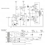
OK. This is the most stable configuration I could think of. If it works, if should give a sensitivity of around 600mV for full power. The capacitors across the 1M5 feedback resistors need to be about 1pF - which is very small, and getting towards the value of the capacitance between the end caps of the 1M5 resistors, so they're probably not needed. Both the valves shown are ECC82.
Try it, by all means, but don't spend significant money on it, as it may not be possible to get it to work properly. If it can be made to work without oscillating, there are all manner of things that could be done to make it sound really nice.
Try it, by all means, but don't spend significant money on it, as it may not be possible to get it to work properly. If it can be made to work without oscillating, there are all manner of things that could be done to make it sound really nice.
Attachments
Hi,
Sorry for not replying sooner, had a busy couple of days.
Wow - thank you very much for your help!
3 questions that arise:
1)What are those 1Mohm resistors you used in series in the input stage?
2) Am i mistaken or did you use DC coupling between the first and second stage?
3) Why did you chose to use ECC82's in the input stage instead of 2 6au6's like in the original desing? I'm not complaining or anything (lol), just curious as to why you think it's better to do it with a double triode instead of 2 pentodes? (I like the idea though - maybe i can can be addapted further and try out a 6SN7 instead of the ECC82 ).
Cheers,
Guy.
Sorry for not replying sooner, had a busy couple of days.
Wow - thank you very much for your help!
3 questions that arise:
1)What are those 1Mohm resistors you used in series in the input stage?
2) Am i mistaken or did you use DC coupling between the first and second stage?
3) Why did you chose to use ECC82's in the input stage instead of 2 6au6's like in the original desing? I'm not complaining or anything (lol), just curious as to why you think it's better to do it with a double triode instead of 2 pentodes? (I like the idea though - maybe i can can be addapted further and try out a 6SN7 instead of the ECC82
).Cheers,
Guy.
The 1M resistors are grid-leaks to hold the grids of the input valves at 0V. The two stages are DC coupled. Triodes (even ECC82) produce less distortion, plus a double triode is cheaper and requires less metalwork than a pair of pentodes.
If the thing works without oscillating, I would far rather use 7N7 or 6SN7 than ECC82 (much lower distortion). But see if it works with ECC82 first...
If the thing works without oscillating, I would far rather use 7N7 or 6SN7 than ECC82 (much lower distortion). But see if it works with ECC82 first...

- Status
- This old topic is closed. If you want to reopen this topic, contact a moderator using the "Report Post" button.
- Home
- Amplifiers
- Tubes / Valves
- From stereo to monoblocks