In first time thank you, I was time ago reading your comments (very nice), but for problems with my english (is very poor) never was the pass of register.
Finally I´m registered because I have one Music Angel with EL34B model XD500-MKIII, I´me very, two week ago I replaced all chinese valves for a newTAD valves, the sound is improving, but I believe that is needed adjust bias.
Please can you help me I need schematics, ot tunnings for this.
P.D:
It´s my first valve amplifier, I´m happy, but, I don´t know, before I had a stereo yamha. My speakers are a B&W684
Thanks and I wait your responses.
Great forum.
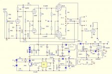
Here is the published circuit diagram. It may not fit exactly with your amp, since there has been some changes to components over time.
For bias adjustment, first measure the cathode resistors for the output tubes and note the value.
Let us assume they are 5 ohm (it may be two 10 ohm in parallel, one on each side of the circuit board). They are located on the circuit board at the back.
If you want to set the bias for an idle current of 40mA, there should be 0.2V across the cathode resistors.
The bias is adjusted with the blue trim-pots on the power-supply board.
There is one for each tube. After you have identified which one correspond to each tube you may want to mark them with a permanent marker.
NB: There is 400V inside so be careful!
Use clips on your test-leads so you do not need to hold them.
Use one hand for adjustment. The other hand on your back!
Svein.
Attachments
Thank you for your very quick information, I´ll try to investigate whit this schematichs.Here is the published circuit diagram. It may not fit exactly with your amp, since there has been some changes to components over time.
For bias adjustment, first measure the cathode resistors for the output tubes and note the value.
Let us assume they are 5 ohm (it may be two 10 ohm in parallel, one on each side of the circuit board). They are located on the circuit board at the back.
If you want to set the bias for an idle current of 40mA, there should be 0.2V across the cathode resistors.
The bias is adjusted with the blue trim-pots on the power-supply board.
There is one for each tube. After you have identified which one correspond to each tube you may want to mark them with a permanent marker.
NB: There is 400V inside so be careful!
Use clips on your test-leads so you do not need to hold them.
Use one hand for adjustment. The other hand on your back!
Svein.
Thanks again.
- Status
- This old topic is closed. If you want to reopen this topic, contact a moderator using the "Report Post" button.