Howdy folks,
Here is an EL34 schematic I would like to build, but I was wondering if there was a way to change the circuit to just one 6SL7 (as it is a dual triode) to drive the EL34's instead of running the two sections in parallel as shown.
http://angela.com/stereosingle-endedel34hi-fiamplifier.aspx
Could someone help me figure this out?
Very easy to do. You build one channel using one half of the 6SL7, using the 6SL7 pin numbers outside the parentheses. Then, build the other channel using the other half, using only the 6SL7 pin numbers inside the parentheses.
Just one promlem...IMHO it's a bad idea. The 6SL7 is wimpy tube with low transconductance. The designer doubled it up for a reason, it was not some cosmetic whim.
Just one promlem...IMHO it's a bad idea. The 6SL7 is wimpy tube with low transconductance. The designer doubled it up for a reason, it was not some cosmetic whim.
ambience exists said:Howdy folks,
Here is an EL34 schematic I would like to build, but I was wondering if there was a way to change the circuit to just one 6SL7 (as it is a dual triode) to drive the EL34's instead of running the two sections in parallel as shown.
http://angela.com/stereosingle-endedel34hi-fiamplifier.aspx
Could someone help me figure this out?
They are not run parallel, the schematic shows the complete amp with two separate channels, each driven by one half of the 6SL7

look closer at the image- the numbers by the lugs have numbers in parenthesis which is the other half of the tube. There is an asterisk over to the right which says that the two triodes in each tube are run parallel. I am assuming that there would be just a simple wire from say the cathode of the first section to the other section.
Re: Re: SE EL34 schematic HELP: from two 6SL7's to One?
A 6SN7 doesn't have enough gain. This isn't Scrabble. You don't design an amp by seeing what letters you have.
Your was a little premature. RTFS
ambience exists said:now how about swapping the 6sl7 for a 6sn7? What would that do to my component values?
A 6SN7 doesn't have enough gain. This isn't Scrabble. You don't design an amp by seeing what letters you have.
Miniwatt said:They are not run parallel, the schematic shows the complete amp with two separate channels, each driven by one half of the 6SL7
Your
was a little premature. RTFS ambience exists said:look closer at the image- the numbers by the lugs have numbers in parenthesis which is the other half of the tube. There is an asterisk over to the right which says that the two triodes in each tube are run parallel. I am assuming that there would be just a simple wire from say the cathode of the first section to the other section.
 I'm sorry, you're right, I didn't look further than the schematic. Let's just say I wouldn't draw it that way
use mosfets
'sl7 drives mosfet follower, drives EL34...
ambience exists said:Howdy folks,
Here is an EL34 schematic I would like to build, but I was wondering if there was a way to change the circuit to just one 6SL7 (as it is a dual triode) to drive the EL34's instead of running the two sections in parallel as shown.
http://angela.com/stereosingle-endedel34hi-fiamplifier.aspx
Could someone help me figure this out?
'sl7 drives mosfet follower, drives EL34...
Plugging in a 6SN7 would indeed change your component values, but as was mentioned there probably wouldn't be enough gain. Unfortunately, true, you cannot just plug it in because it too is an octal tube. The above is a good recommendation though, having the SL7 drive a FET to drive the EL34. You could also do a mu stage with a pair of depletion FET's or a nice juicy pentode (D3a comes to mind, or 12HG7 maybe).
This is a very similar design to Tubelab's Simple SE, you could look into that as an option too. It just uses a current source loaded 12AT7 instead of the 6SL7 to drive just about any common octal power tube (EL34, KT88, 6L6, etc...). There is a ton of support around for the Simple SE, lots of builds floating around. Great easy to build board that is open to options; cathode feedback, triode/UL outputs, all sorts of different bias settings, LED biased 12AT7 (losing a cap and a resistor), maybe removing the 10M45 and rolling some current sources (a la Pimm, Camille, or others), tube rolling, the fun just can't end.
http://www7.taosnet.com/f10/mustage.html
http://www.tubelab.com/
Attached is the dual depletion FET source, for a "FET mu stage" you would take the signal from the "Low Z Out" attachement. The diagram is thanks to Poinz by the way.
Cheer
James
Attachments
Hi,
driving the 100...150pF of Miller capacitance of a trioded EL34 to (a little bit more than) 56Vpp as per the Angela circuit cannot be done with a single section of a 6SL7 with a reasonable slew rate. You will encounter high freq roll-off way too early, except you use an AM radio as a programme source.
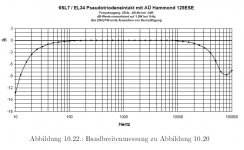
The paralleled sections as shown will do okay, especially considering the limited bandwidth capabilities of the suggested 125ESE OPT.
Again, considering the limitations of that OPT, some suggestions already given here in this thread like MOSFET source follower drivers or mu-stages are thoughtless and unneccessary overkill.
Actually, a "mighty" driver would "unmask" the shortcommings of the cheap OPT: With a "mighty" driver in this zNFB design you would get all sorts of phase shifts at upper freqs. With the circuit as is, you get a smooth and reasonable high freq roll-off.
The Angela circuit - as is - sounds surpirisingly good to me (if you like "singing" amps), not only considering the lowish component price/investment. Actually, it is a good example of a straightforward and homogeneous implementation with limited ressources.
Bandwidth plot of the original circuit (using two 6SL7 sections paralleled) attached.
Regards,
Tom Schlangen
driving the 100...150pF of Miller capacitance of a trioded EL34 to (a little bit more than) 56Vpp as per the Angela circuit cannot be done with a single section of a 6SL7 with a reasonable slew rate. You will encounter high freq roll-off way too early, except you use an AM radio as a programme source.
The paralleled sections as shown will do okay, especially considering the limited bandwidth capabilities of the suggested 125ESE OPT.
Again, considering the limitations of that OPT, some suggestions already given here in this thread like MOSFET source follower drivers or mu-stages are thoughtless and unneccessary overkill.
Actually, a "mighty" driver would "unmask" the shortcommings of the cheap OPT: With a "mighty" driver in this zNFB design you would get all sorts of phase shifts at upper freqs. With the circuit as is, you get a smooth and reasonable high freq roll-off.
The Angela circuit - as is - sounds surpirisingly good to me (if you like "singing" amps), not only considering the lowish component price/investment. Actually, it is a good example of a straightforward and homogeneous implementation with limited ressources.
Bandwidth plot of the original circuit (using two 6SL7 sections paralleled) attached.
Regards,
Tom Schlangen
Attachments
Tom,
Thanks for the helpful word on my project! I will stick to the schematic, I want the amp to work, not be a science experiment... I listen to mostly jazz and string quartet's and ambient/drone based music. How do you think these EL34's would do in these musical situations. My ideal choice would be DHT 300B but alas, experience and money funds are not yet high enough to experiment with such triode.
How quiet is your amp? Will I have to pay very close attention to the ground scheme?
What speakers do you use? I need to match these well, I am thinking of some OB's
peace,
((AE))
Hi AE,
I bet you will like it for that type of music. It is good with chamber music, choirs and human voices, too. Maybe a bit too good (due to a good deal of even harmonics generated).
It ain´t no 300B amp killer, but it can give a taste of what can be done for a very reasonable component price/investment. I mean, you can get all parts for less than what you have to pay for a single NOS 300B...
In general with highish impedance tube circuits (compared to solid state stuff), a clean wiring (including grounding scheme) is a must. There are several strategies people swear by, which can lead to opinion wars. In the case of this amp, I used sort of a multiple star grounding topology: Per channel: One star for all parts around the driver, one star for all parts around the power stage. One central star for the PSU (common to both stereo channels), to which the other four "sub"-stars of the drivers and powerstages also were returned. For the inputs (from RCA jackets to the driver stages) I used the "patch cable approach". The central star at the PSU connected to mains ground by a 10Ohms/10Watt non-inductive resistor.
First tests at my home were done at German Isophon Avalon speakers (D´Appolito principle + integrated bandpass woofers for each spkr). My father in law just used a pair of rather inexpensive (about 600 Euros / pair) French Focal speakers.
He and I have in common, that we don´t want to listen to speakers, so to say. Said Isophon and Focal speakers are of the neutral, medium efficiency side.
Regards,
Tom Schlangen
I listen to mostly jazz and string quartet's and ambient/drone based music. How do you think these EL34's would do in these musical situations.
I bet you will like it for that type of music. It is good with chamber music, choirs and human voices, too. Maybe a bit too good (due to a good deal of even harmonics generated).
My ideal choice would be DHT 300B but alas, experience and money funds are not yet high enough to experiment with such triode.
It ain´t no 300B amp killer, but it can give a taste of what can be done for a very reasonable component price/investment. I mean, you can get all parts for less than what you have to pay for a single NOS 300B...
I have not measured that, and this largely depends on actual implementation (shilding, wiring. component placement, etc).How quiet is your amp?
Will I have to pay very close attention to the ground scheme?
In general with highish impedance tube circuits (compared to solid state stuff), a clean wiring (including grounding scheme) is a must. There are several strategies people swear by, which can lead to opinion wars. In the case of this amp, I used sort of a multiple star grounding topology: Per channel: One star for all parts around the driver, one star for all parts around the power stage. One central star for the PSU (common to both stereo channels), to which the other four "sub"-stars of the drivers and powerstages also were returned. For the inputs (from RCA jackets to the driver stages) I used the "patch cable approach". The central star at the PSU connected to mains ground by a 10Ohms/10Watt non-inductive resistor.
What speakers do you use?
First tests at my home were done at German Isophon Avalon speakers (D´Appolito principle + integrated bandpass woofers for each spkr). My father in law just used a pair of rather inexpensive (about 600 Euros / pair) French Focal speakers.
He and I have in common, that we don´t want to listen to speakers, so to say. Said Isophon and Focal speakers are of the neutral, medium efficiency side.
Regards,
Tom Schlangen
- Status
- This old topic is closed. If you want to reopen this topic, contact a moderator using the "Report Post" button.
- Home
- Amplifiers
- Tubes / Valves
- SE EL34 schematic HELP: from two 6SL7's to One?