Hi all
I'm in to measure my DIY amplifiers and have a clue on what to measure but, .... is there any major standards, for example a headphoneamp and what to measure?
I'm in the middle of finsihing my headphoneamp which I have had fantasys of for at least 30 years. My time here on earth is limited, I have discovered, but I want to present my amp here as a thank you to all help I got here, before I go dead.") Don't be sorry I have no disease that I know yet, but I feel that time is my enemy when it comes to do someting for yourself and also a bit unusual project, exept go to the work to get your earning everyday... Then your time for that day is doomed. ( at least for your nr.1 hobby )
Don't be sorry I have no disease that I know yet, but I feel that time is my enemy when it comes to do someting for yourself and also a bit unusual project, exept go to the work to get your earning everyday... Then your time for that day is doomed. ( at least for your nr.1 hobby )
This Q could have been at some other cathegory but for now it's my tubed OTL headphoneamp I want to have some figures for. I have just built it with ears. Thats normally against my religion as a measuring engineer. Thats why I find that this final measuring is really going to bring this amp to a degree of confirmation
I have read a lot on the net the last few years and preferably mostly John Broskies Tubecad site but I have also two books from Morgan Jones. Tube amplifiers (rev.3) and Building tubeamplifiers.
I know of some softwares, and I have also used some, but I want your opinion.
Please give me your advise on what a spec should include. What tests get the most attentions?
I'm in to measure my DIY amplifiers and have a clue on what to measure but, .... is there any major standards, for example a headphoneamp and what to measure?
I'm in the middle of finsihing my headphoneamp which I have had fantasys of for at least 30 years. My time here on earth is limited, I have discovered, but I want to present my amp here as a thank you to all help I got here, before I go dead.
Don't be sorry I have no disease that I know yet, but I feel that time is my enemy when it comes to do someting for yourself and also a bit unusual project, exept go to the work to get your earning everyday... Then your time for that day is doomed. ( at least for your nr.1 hobby ) This Q could have been at some other cathegory but for now it's my tubed OTL headphoneamp I want to have some figures for. I have just built it with ears. Thats normally against my religion as a measuring engineer. Thats why I find that this final measuring is really going to bring this amp to a degree of confirmation
I have read a lot on the net the last few years and preferably mostly John Broskies Tubecad site but I have also two books from Morgan Jones. Tube amplifiers (rev.3) and Building tubeamplifiers.
I know of some softwares, and I have also used some, but I want your opinion.
Please give me your advise on what a spec should include. What tests get the most attentions?
"I'm in to measure my DIY amplifiers and have a clue on what to measure but, .... is there any major standards, for example a headphoneamp and what to measure?"
No, not really. For my designs, I basically measure the -3db(v) frequency response, and run an input/output comparison check. I whipped up a little circuit from a quad op-amp IC. One section is a linear subtractor, made with 0.1% ultraprecision, 0.125W, metal film resistors. Two others form voltage followers to drive the subtractor inputs, the last section being a basic voltage amp connected to the output of the subtractor.
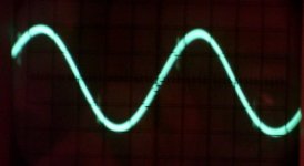
The gNFB summing node provides a convenient output sampling point. Next, just adjust the input going into the subtractor with a pot to get the deepest null. What's left over must be distortion. In the attached photo, you can see that what's left is basically a sine wave, and the null would be deeper if it wasn't for phase shift. The main artifacts left over are slight switching glitches as each final goes into plate current cutoff (Class AB1 operation here).
Another test is the Twin-T, used to see what kinds of harmonics you're getting. That's another thing: 6BQ6GTBs produce mainly h3, whereas 807s are producing more of the dissonant high order harmonics. That, too, determined design choices: local NFB for 807s, and just gNFB for 6BQ6GTBs.
Attachment: 166Hz (1.0mS / 50mV)
No, not really. For my designs, I basically measure the -3db(v) frequency response, and run an input/output comparison check. I whipped up a little circuit from a quad op-amp IC. One section is a linear subtractor, made with 0.1% ultraprecision, 0.125W, metal film resistors. Two others form voltage followers to drive the subtractor inputs, the last section being a basic voltage amp connected to the output of the subtractor.
The gNFB summing node provides a convenient output sampling point. Next, just adjust the input going into the subtractor with a pot to get the deepest null. What's left over must be distortion. In the attached photo, you can see that what's left is basically a sine wave, and the null would be deeper if it wasn't for phase shift. The main artifacts left over are slight switching glitches as each final goes into plate current cutoff (Class AB1 operation here).
Another test is the Twin-T, used to see what kinds of harmonics you're getting. That's another thing: 6BQ6GTBs produce mainly h3, whereas 807s are producing more of the dissonant high order harmonics. That, too, determined design choices: local NFB for 807s, and just gNFB for 6BQ6GTBs.
Attachment: 166Hz (1.0mS / 50mV)
Attachments
1.
Make sure the fuse is in place.
Have a fire extinguisher handy.
Disconnect amplifier circuits from power supply circuit.
Look away.
Turn on.
Make sure your power supply is working correctly.
Turn it off. Wait for capacitors to discharge.
Connect amplification circuits.
Connect a (substantial wattage) dummy load.
Turn on.
Make sure there is no DC voltage at the outputs.
2.
Check amplification factor (gain). MUST be the same in both channels.
Turn volume down to 1%. With no input, listen to the circuit, and slowly increase the volume - any hum or hiss?
Turn volume down to 1%. Connect input, listen to the circuit, and slowly increase volume - sound quality?
3.
Check bandwidth.
Have a read...
http://www.rane.com/pdf/note145.pdf
http://en.wikipedia.org/wiki/Audio_system_measurements
http://en.wikipedia.org/wiki/Audio_quality_measurement
Thanks Miles Prower and Gordy.
I will try some software and my 196/24 bit M-audio to measure and look at the THD and which flavour it is.
Thanks for the links Gordy.
I have allready done the first three checks.
This all tube headphoneamp is dead silent when there is no music playing.
Bandwith measured today to 1.3MHz with 300 ohm R load and 1MHz with the Sennheizer HD-650. The headphones gives an overshot on squarewaves and +3dB at 100kHz f.e.
Is this something I should compensate for ?
I hope I can share the design and schematic with test figures later on in another thread.
IMHO, noise and frequency response are first in line. I want to see -3 dB points of about 3 Hz and 50 kHz or better. This to insure very flat response and freedom from problems in the 20-20k band. There seems to be a general consensus that THD numbers are worthless, but from an engineering POV I want to know them anyway. They tell me I haven't screwed up in any major way. What I also want to see is the THD residual output on a scope. A full FFT is enlightening, but there's absolutely no consensus on how much of what is good or bad. My experience, having used various different analog THD analyzers is that PC sound card analysis can be useful and powerful, but the results are wrong as often as they are right, at least until you get it all figured out. For me, the analog equipment is absolutely necessary as a reality check. Finally, there are some operational things I check for like pop on turn-on and turn-off, susceptibility to RF and line noise, regulation at low line if applicable, power consumption, power factor, surge if it's a big amp. Does it overload gracefully? That should keep you busy for a while!
Miles Prower said:Another test is the Twin-T, used to see what kinds of harmonics you're getting.
Miles,
Are you referring to using a Twin-T notch filter to remove the fundamental and examining the harmonics, or do you use a different test method?
Thx,
- Status
- This old topic is closed. If you want to reopen this topic, contact a moderator using the "Report Post" button.
- Home
- Amplifiers
- Tubes / Valves
- Measuring technics practical, the allaround reference method?