This idea came to me after doing some work with vacuum fluorescent display tubes. If the filament is lit with DC then long segments will be bright at one end and dim at the other so using AC solves this problem.
I used a 7404 hex inverter set as an oscillator of around 200Khz and took the output and used it along with its inversion and fed that into an L298 bridge motor driver. The result is an AC square wave. This got me thinking about trying it with DHTs.
The general agreement is DHTs sound best with AC filaments and low voltage switching supplies are dirt cheap. So use an opamp like an OPA340 (single supply and rail to rail) as sine oscillator driving a mosfet bridge. Get some logic level low Rds mosfets and you could probably mount all 4 on the same heatsink. Use a frequency of maybe 400-500Khz and I don't see how that would be any worse than dealing with 60Hz hum.
astouffer said:The general agreement is DHTs sound best with AC filaments and low voltage switching supplies are dirt cheap.
My sense is that DHTs sound best not because of AC, but in spite of it. With just about any DC supply, if you look at the AC signal current path, it travels through at least one cap (either after the regulator, or on the end of the RC or LC filter) which degrades the signal. With AC, it is just through a transformer, which likely does less damage. The one DC exception is a CCS supply, and a CCS worth using has no caps after the CCS, and blocks AC meaning that the AC signal current avoids the capacitors.
When doing the initial design on the Tubelab SE I found the following. I started with an AC powered 45. It was fed in the usual way with a hum balance pot across the filament transformer, wiper grounded. I could indeed null the hum like you are supposed to. The prototype was built and I was playing with things like driver transformers, cathode followers and eventually the mosfet driver circuit that I now call PowerDrive. All along I sensed that something just didn't sound quite right. It was most obvious when I plugged an acoustic guitar straight into the amp and plucked a single string. There was a fuzziness that didn't belong. It dissapeared as the note decayed.
It was at about this time that I discovered the FFT analyzer. This new design tool uncovered the "fuzz" imediately. It was IMD products created from the fundamental guitar note mixing with the 60Hz present on the 45 filament. The output had 60Hz sidebands that were strongly dependent on the level of the fundamental note aven though there was very little 60Hz present in the output. These IMD products appear well before clipping, and slowly drop off as the amp hits hard clipping.
I substituted a DC power supply for the filament transformer and the fuzz (both audible and measured) was gone. This is why the Tubelab SE uses a DC filament supply. One side of this supply is directly grounded so there are no added caps in the signal path. I realize that this flies in the face of the "DHT's sound best on AC crowd", but it seems to work for me.
I briefly experimented with high frequency AC heating a few years ago. I got fruatrated with blown mosfets and gave up. I think (but have not yet proven) that you want your AC frequency to be a good deal above the frequency response of your OPT to keep IMD to a minimum. This should be easy with todays parts. If the frequency is high enough, a square wave may be OK. Again this is an unproven guess.
Have given the subject some thought and wonder if DC is the best as the potential is different from one end of the cathode to the other. I haven´t the knowledge in deeper tube theory to know if this a bad thing.
Anyway the idea of high-frequency heaters, why not fed from a CT grounded transformer, appeals to me.
At the moment I am planning a compactly built trioded 813 SE(got a pair NOS of Philips QB2/250A at a hamfest nearby ) where my idea was to ground one end and feed the heaters with a SMPS followed by a CCS. Same capfree solution as dsavitsk mentioned.
If there was a hf-solution ready I would go for that. P. Millet have a thing about hf-heaters on his site but is was made a while ago.
")
Have given the subject some thought and wonder if DC is the best as the potential is different from one end of the cathode to the other.
On the 45 tube the potential difference between one end and the other is 2.5 volts the bias voltage can be in the 50 volt range. I don't think 5% is a big deal. The 300B is worse at around 8%. Ditto the 845. The problem lies with high Mu tubes like the 811A The filament voltage can be higher than the bias voltage for some operating conditions. Here only part of the filament will be used when fed by DC. Coincidentally these tubes are the worst offenders in the hum department. If you want to test out a HF heating system the 811A would be the worst case test subject.
I really think you would be opening up a BIG can-o-worms by running that high a F. Coming from one who understands analogue(sp?) TV on a basic level....low end RF brings out unanticipated consequences.
One that might crop up would be an electrical stiction of the filiments as such the voltages the filiments "see" would rise.
George is right....even at 60 Hz problems crop up...NOW you run a square wave and you can be certain something unexpected will rise up to foul things up........experiment and see.
__________________________________________________Rick....
Ok this is only a proof of concept and I really don't have an immediate need but this is still interesting.
That looks too much like my original fet smoker. It took a few blown fets to figure out that H bridges only work with square waves. Apply a sine wave and you get "shoot through". This is what happens when the top and bottom fets turn on at the same time. The power supply "shoots through" the fets leaving bullet holes!
The design that worked best resembled a push pull amp with mosfets where the tubes belong. The OPT was a 1 inch toroid. Efficiency sucked but I was using 20 year old hamfest mosfets.
 :
:
Maybe you've all already seen it, but I did some work with this a while back:
http://www.pmillett.com/hf_fil.htm
I was concerned with all the HF energy in a 100kHz square wave, so I took a quasi-resonant approach.
This worked pretty well, though I never had time to perfect it. Really the biggest problem was that the voltage regulation side was not very efficient - I really should have used a synchronous rectifier.
Definitely not as easy as it first seems.
Pete
Re: Re: Yet another DHT filament supply
A quick and dirty AC cheat currently on the bench: uprate the filament transformer a few amps, float the centre tap, put a couple very low value series resistors across the filament and use the centre as cathode. A 2A3 for example has 1 ohm + 1 ohm across it, an effective cathode to centre tap of 1/2 ohm pure resistance. It 'wastes' a whole couple watts.
dsavitsk said:My sense is that DHTs sound best not because of AC, but in spite of it....
A quick and dirty AC cheat currently on the bench: uprate the filament transformer a few amps, float the centre tap, put a couple very low value series resistors across the filament and use the centre as cathode. A 2A3 for example has 1 ohm + 1 ohm across it, an effective cathode to centre tap of 1/2 ohm pure resistance. It 'wastes' a whole couple watts.
By the way, my belief pretty much aligns with dsavitsk...
From a noise and IMD standpoint there's no doubt that DC is better. OK, there may be some doubt: I really do believe one component of the "tube sound" some people crave includes filament IMD. But that's another topic...
I think the key is to remove the filament supply from the signal path. You can do this with a CCS (high AC impedance means signal goes elsewhere), or a common mode choke.
The center tap transformer works too, but then you must have AC. If you push the AC to a high enough frequency I think you're OK (as tubelab said, push the IMD products above the OPT's BW).
Pete
Reviving an old thread, because I'm curious, has anyone made any progress? I'm in the planning stages of a DHT based headphone amp, and will probably start with a DC filament supply. I am also considering the ccs+gyrator filament supply from another thread.
But still, back to this idea for a moment. Instead of a high frequency, I am thinking of a very low frequency wave, below 5Hz, say. Would that be less/more audible? Another idea is to reverse polarity on the filament, but that does not seem it would be as smooth. Any comments?
But still, back to this idea for a moment. Instead of a high frequency, I am thinking of a very low frequency wave, below 5Hz, say. Would that be less/more audible? Another idea is to reverse polarity on the filament, but that does not seem it would be as smooth. Any comments?
Nothing to show as of yet. You basically need a good solid state amplifier fed with a high frequency sine wave and a tube filament as a load. Thats no more crazy than the few articles in AudioXpress about using some Crown PA amps as an AC power supply.
One crazy idea I thought of was using those cheap class D amps from ebay as a filament supply. They run from a single voltage supply and need minimal heatsinking. Not sure about their upper frequency limit though...
One crazy idea I thought of was using those cheap class D amps from ebay as a filament supply. They run from a single voltage supply and need minimal heatsinking. Not sure about their upper frequency limit though...
ikoflexer said:Reviving an old thread, because I'm curious, has anyone made any progress? I'm in the planning stages of a DHT based headphone amp, and will probably start with a DC filament supply.
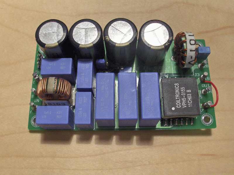
Here's my DHT headphone amp. It is quiet enough that you can't tell if it's on without looking to see if the tubes are glowing.
I use a voltage doubler off the 6.3v winding followed by a linear regulator then with a CCS on each tube. The CCS is just a LM317 with a resistor.
An externally hosted image should be here but it was not working when we last tested it.
ikoflexer said:Is there a specific ccs that you use/recommend in this application? I couldn't find details about it on your site.
dsavitsk said:The CCS is just a LM317 with a resistor.
A writeup of how this works: http://diyparadise.com/yhlmccs.html
I haven't found anything that works better while dropping only a few volts. I am sure there is something, I just don't know what it is. One good thing is that there seems to be less variation in LM317's than in depletion mode mosfets or jfets meaning that using fixed resistors works OK.
Note however that the 71a only needs 250mA, so if you are using a 2a3 or similar this is going to be a lot more difficult.
Also note that this arrangement is somewhat unusual in that due to the grounded filament and fixed grid bias, I am able to use the same winding for both filaments.

- Status
- This old topic is closed. If you want to reopen this topic, contact a moderator using the "Report Post" button.
- Home
- Amplifiers
- Tubes / Valves
- Yet another DHT filament supply