(With apologies to O.H. Schade; the highest honor is intended)
I've become curious about this triode emulator circuit. The effective
Rp approaches 1/gm. (kenpeter, just point me to the post where you
already show this ;-) I can't find it...)
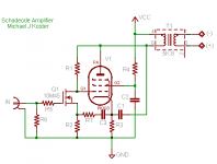
It should be possible to produce a triode characteristic using a
pentode like an 807 to approximately emulate a 300B in an SE amp
like this one.
One issue is the Rp is really too low. DC stability will be poor, but
the LW trick should cancel PS ripple.
I think maybe something like a resistor divider instead of the
open-drain type connection... Maybe a CCS instead of the cathode
resistor. If it was push-pull it would resemble a Tabor. SETabor?
Spudly Hybrid Half-a-Tabor?
The 10M45 will self-bias at about 3 volts at 3-4 mA DC current in the
FB loop
The gain is ~R1/R2 to the OPT primary, equivalent to the product
of in-circuit mu for all stages in the equivalent multistage amp.
I'm rigging up a simple curve tracer to demonstrate the triode-like
characteristic.
Michael
I've become curious about this triode emulator circuit. The effective
Rp approaches 1/gm. (kenpeter, just point me to the post where you
already show this ;-) I can't find it...)
It should be possible to produce a triode characteristic using a
pentode like an 807 to approximately emulate a 300B in an SE amp
like this one.
One issue is the Rp is really too low. DC stability will be poor, but
the LW trick should cancel PS ripple.
I think maybe something like a resistor divider instead of the
open-drain type connection... Maybe a CCS instead of the cathode
resistor. If it was push-pull it would resemble a Tabor. SETabor?
Spudly Hybrid Half-a-Tabor?
The 10M45 will self-bias at about 3 volts at 3-4 mA DC current in the
FB loop
The gain is ~R1/R2 to the OPT primary, equivalent to the product
of in-circuit mu for all stages in the equivalent multistage amp.
I'm rigging up a simple curve tracer to demonstrate the triode-like
characteristic.
Michael
Attachments
LW don't work unless the driving device is a triode or triode emu
with somewhat less than infinite plate resistance... I don't think
you have 10M45 properly set up for compatibilty with that (yet).
Its probably easier bias the required drain to gate "4th circuit"
with an enhancement device anyway.
To be perfectly honest, I'm not yet sure how your version works.
Mine ends up as an inverting P-Channel Triode emulator... Yours
is N-Channel, but appears to be non-inverting. Go figure...
Maybe this was the old thread you were looking for?
Screen Driven Dissimilar Pentode SE Anti-Triode Spud
Close to "Spudly Hybrid Half-a-Tabor" as your gonna get.
http://www.diyaudio.com/forums/showthread.php?s=&threadid=126803&highlight=
I'm not sure I had all the details entirely figured out...
But you can see the voltage divider from plate to cathode.
And the driving device is set up as a high impedance voltage
controlled current source, linearized by cathode feedback.
It tickles a drive voltage to appear upon the central node
of the Schade feedback network, without adding any new
resistance path to muck up the math...
I chose to drive G2. Like I said earlier, easier to bias an
enhancement device. But I doubt there is enough gain
here to make the cave drawings workable.
I can't rememeber why I put the load under the Cathode
instead of over the plate. Perhaps just to show that in
this unique case, the placement made no difference???
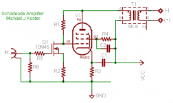
Your Ultrapath cap C1 makes the Cathode ripple with B+.
The high impedance of Q1's drain compared R1 may also
present the full B+ ripple to appear upon the grid.
I'm not sure that C3/R7 do anything useful, if thrown at
the circuit hoping they would act as-if Loftin White's CHB...
You already have the necessary hum on all points except
maybe the screen.
If PSRR is your goal, the Screen cap should be referenced
to B+ rather than GND... As everything else seems to be...
kenpeter said:Your Ultrapath cap C1 makes the Cathode ripple with B+.
The high impedance of Q1's drain compared R1 may also
present the full B+ ripple to appear upon the grid.
I'm not sure that C3/R7 do anything useful, if thrown at
the circuit hoping they would act as-if Loftin White's CHB...
You already have the necessary hum on all points except
maybe the screen.
If PSRR is your goal, the Screen cap should be referenced
to B+ rather than GND... As everything else seems to be...
Good point. The ripple voltage appears everywhere but the
screen. Then this should be the way.
Thanks!
Michael
PS, yes, the unstable N-channel anti-fetron with a half-life of only
a few weeks
Attachments
- Status
- Not open for further replies.