Red lines represent a resistive network that causes
1V of NFB at the gate for 5V at the drain, thus Mu=5
for this example. Just as OHSchade (RCA 6L6 fame)
taught us this trick for Pentodes back in 1938.
Of course the complication is the FETron gate isn't
a high impedance anymore... Takes another FET to
buffer the input when a high impedance is required.
Depending on the circuit, that sort of buffer is not
always necessary. Like between the stages of the
Aikido would be pointless. But at the very input, it
might be critical.
smoking-amp said:It occured to me that the bottom device could be a high gm part (Mosfet) and the top load device a low gm tube (or diode) and still get SE triode results (output off the center tapped top Rk).
Don
Gm is not constant in a FET, how is this supposed to add up to
model a Triode? I'm not yet ready to say that it doesn't, only I
need some further explanation to understand your intent.
If you recall the thread(s) "SE Diode" I tried something similar,
where Mu was computed separately from plate resistance. But
struggled with fake triode curves that were too textbook perfect.
All copies of the same Vacuum Diode, did not lean to the right
as real Triodes do.
I've since noticed the Triode Region of certain IGBTs contains a
very realistic set of leaning curves with Mu nearly equal to Zero.
This would make a great reference diode for "plate resistance".
And DC control of this grid, would allow one to dial in a desired
static curve for "perfect" mode operation, optionally with an AC
variable "lean to the right."
If Mu and plate resistance are correct, GM takes care of itself.
The same IGBT at slightly different operating point has GM > 3
Amperes per Volt! Of course, this is numbed down to the GM
required by the emulation by the other two factors.
smoking-amp said:Maybe Lineup is using the Lovoltech parts for both top and bottom devices of the 1st stage and they are operating in their low voltage triode region.
Would want matched parts then as SY indicated.
Same for the output stage too.
Top and bottom just have to match characteristics, even if 2 power law instead of 3/2 power devices.
Don
there's no need to match top & bottom
there are 2 resistors in Aikido, 1 MOhm
a voltage divider
to set gate operation voltage of second stage follower
For JFET I just lowered this resistance a bit.
This resistance will stablize Operation Point, as well as reduce gain.
Remember what I told you, my circuit has got +15 dB only = x5.5
")
The upper JFET of first stage is operating as a CCS
.. and just to adjust one resistor to set Current
and so get gate operation point of Output stage at 12.0 Volt
= 50% of 24 Volt
------------------
This lowered gain is also a bit of secret of the great performance of my circuit.
Anyone that let his tubes or semiconductors do more gain than needed is not after Hi-fi.
He is out to destroy the original sound signal and let his devices do this.
Whether he knows this, or not.
If I wanted this, I would put one CAP across Input JFET source resistor
and use as High divider Drain Resistors as possible.
This would render maximal gain and maximal destruction of of input signal.
Even more clue this circuit does not behave like an Aikido.
Aikido is complementary loaded by its SRPP totems, not
resistively by the bias fixing network.
Adding a lossy resistive load between stages is a good
trick, considering what you have chosen to drive it with.
But lets be clear that resistive loading after a Mu stage
that has no specific Mu, in the "Triode Region" (if at 12V
per drain you are even down there at all). Is not by itself
capable of transforming any JFET to behave like a Triode.
Aikido is a circuit highly optimized specifically for Triodes.
You can't blindly drop in FETs any more than you can drop
in Pentodes screened to B+. They don't load like triodes
without additional trickery to fake an intrisic Mu that you
seem willing to overlook.
I'm not saying your circuit won't sim and sound good of its
own unique character. Only that its entirely something else.
"Aikido is a circuit highly optimized specifically for Triodes.
You can't blindly drop in FETs any more than you can drop
in Pentodes screened to B+. They don't load like triodes
without additional trickery to fake an intrisic Mu that you
seem willing to overlook.
I'm not saying your circuit won't sim and sound good of its
own unique character. Only that its entirely something else."
I agree, the schematics may look the same, but the soul is definately different without further fixups.
"Gm is not constant in a FET, how is this supposed to add up to
model a Triode? I'm not yet ready to say that it doesn't, only I
need some further explanation to understand your intent."
With a Mosfet on the bottom (1st stage Aikido) and a diode on top for load, the operation would be like a voltage mirror. The two device curvature characteristics need to match up to get a good constant Mu. So the Mosfet would need to be operated at high enough current so its 2 law curve would drop to 3/2 law.
(I guess its not really the same as the driven-Mosfet / Triode P-P CCS tail scheme, since the diode doesn't control the Mosfet current. Bad analogy on my part earlier.)
Alternately, since gridded tubes act more like 2 law devices due to the grid "island effect", one could just use a diode wired triode on top as already exists in the Aikido, with a Mosfet in 2 law op. region on the bottom.
-------------------------
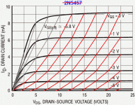
Those Fetron curves look decent, some would be happy to find a triode like them.
--------------------------
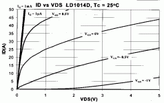
I have attached the Lovoltech LD1014D curves. For Vgs below -1V, they could be decent triode mimics. Probably have square law curvature for Id versus Vgs or Vds.
Don
You can't blindly drop in FETs any more than you can drop
in Pentodes screened to B+. They don't load like triodes
without additional trickery to fake an intrisic Mu that you
seem willing to overlook.
I'm not saying your circuit won't sim and sound good of its
own unique character. Only that its entirely something else."
I agree, the schematics may look the same, but the soul is definately different without further fixups.
"Gm is not constant in a FET, how is this supposed to add up to
model a Triode? I'm not yet ready to say that it doesn't, only I
need some further explanation to understand your intent."
With a Mosfet on the bottom (1st stage Aikido) and a diode on top for load, the operation would be like a voltage mirror. The two device curvature characteristics need to match up to get a good constant Mu. So the Mosfet would need to be operated at high enough current so its 2 law curve would drop to 3/2 law.
(I guess its not really the same as the driven-Mosfet / Triode P-P CCS tail scheme, since the diode doesn't control the Mosfet current. Bad analogy on my part earlier.)
Alternately, since gridded tubes act more like 2 law devices due to the grid "island effect", one could just use a diode wired triode on top as already exists in the Aikido, with a Mosfet in 2 law op. region on the bottom.
-------------------------
Those Fetron curves look decent, some would be happy to find a triode like them.
--------------------------
I have attached the Lovoltech LD1014D curves. For Vgs below -1V, they could be decent triode mimics. Probably have square law curvature for Id versus Vgs or Vds.
Don
Attachments
kenpeter said:I've since noticed the Triode Region of certain IGBTs contains a
very realistic set of leaning curves with Mu nearly equal to Zero.
This would make a great reference diode for "plate resistance".
Mind you the current involved to abuse this IGBT's Triode
Region as a voltage variable curve for computing realistic
"Plate Resistance". Must pass nearly 2 full amps! May not
be a suitable reference for every situation.
These curves look afwully Triodish to me... More so than the
Triode Region of a JFET at similar low voltages. Excepting for
how bizarrely they dogpile on top of each other. Mu is just
about zero. But for an oddball circuit like SE Diode, where a
Mu is computed separately, it may be just the ticket.
Imagine these same curves, but with a regular Mu spacing
padded inbetween.
Triodes consist of three things: Mu, Gm, and Plate Resistance.
None of these three variables are static. All of them vary with
the operating point.
We need only a good realistic model for any two of the above
variables, the third (any of the above) is automatically implied.
Of course if either reference chosen proves inconsistent with
the dynamic behavior of a real triode, forget about the third
dynamic variable behaving correctly.
Attachments
- Status
- This old topic is closed. If you want to reopen this topic, contact a moderator using the "Report Post" button.
- Home
- Amplifiers
- Tubes / Valves
- All FET Aikido