Does anyone have a schematic using 12ax7a, 35z5, 50L6 tubes.
I had an old guitar amp using those tubes and it sounded great but the speaker cone got punctured and it got thrown out.
This was about 8 years ago and before my dad threw it out i grabed the tubes, the transformer, an orange metal cap (at least i think its a cap) can't find it anymore, and the two pots, one for volume and one for tone.
I really liked the sound of that amp, it was clean and loud enough for me, and from what i remember the circuit was fairly simple.
I was just wondering if anybody knows of or has a schematic that used these three tubes and is simple to construct. I tried seaching this forum and the internet but i havn't found anything except a review of another vary similar amp.
http://www.harmony-central.com/Guitar/Data/AGS/300_108_Combo-01.html
Different brand name, mine was trend and had a 12" not 8" driver
Any help would be appreciated
I could probably point you to a schematic, but I won't, since the circuit won't be isolated from the AC line. This is ESSENTIAL for a guitar amp! A close encounter with a mike stand could be your last. My brother uses one like this, a Silvertone, and I replaced the 30 year old cap that 's the only part isolating 115VAC from the guitar strings with a modern, safety rated part.
If there's a power transformer, one of these old parts can smoke and the worst that happens is a fuse will blow. I suggest you look at the designs at http://www.ax84.com
If there's a power transformer, one of these old parts can smoke and the worst that happens is a fuse will blow. I suggest you look at the designs at http://www.ax84.com
I remember when playing on the original amp that i got some sort of electrical feedback through the strings, kinda felt like my hands were on pins and needles, Not painful though and it didn't seem to affect the sound. Would that be the same thing you are talking about?
But basically all i am looking for is the origional schematic using these three tubes, It doesn't even have to have tone control like the origional, just a volume pot, and one input.
But basically all i am looking for is the origional schematic using these three tubes, It doesn't even have to have tone control like the origional, just a volume pot, and one input.
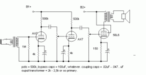
ok, heres the setup. just drew it quick, so but should work pretty good. might want to change it up a bit.
the input transformer is there to stop you from getting 120vAC on you're guitar strings. (might want to put some plastic knobs on the pots too, or isolate them from the chassis, so you dont get zapped there. hehe) I guess a polarized plug would work too, but your house could be wired wrong.
the input transformer is there to stop you from getting 120vAC on you're guitar strings. (might want to put some plastic knobs on the pots too, or isolate them from the chassis, so you dont get zapped there. hehe) I guess a polarized plug would work too, but your house could be wired wrong.
Attachments
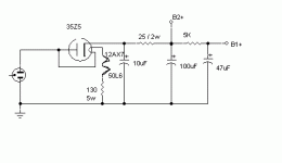
power supply.
neutral should go to ground, albeit it doesnt really matter with the isolation tranny...
didn't look at the data for 35z5 too closely, so you might be able to jack up the first cap some.. maybe the 2nd too.. might hum a little as-is, should be realtivley quiet though.
damn ive got a lot of spelling errors tonight
Moderators Note: this power supply circuit is a SAFETY HAZARD/p10
Attachments
Colt45 said:power supply.
You really need to get a power transformer on that puppy FOR SAFETY SAKE -- power supply circuits directly off the AC were OUTLAWED for a reason. Even just a couple of the old ground fault isolation transformers (run the filiments on a separate one) might do you -- you can usually find these at construction recyclers or 2nd hand stores -- i haven't seen them for more than $5, but i usually pay $2 for them.
I have a stero hifi amp using similar tubes -- a 12av6 (1/2 a 12AX7) for driver. If you aren't driving some passive tone controls the 2nd section of the 12ax7 is unneeded.
dave
I'd be inclined to replace the pot in the 50L6 stage with a fixed resistor and have some NFB from the output tranny to the cathode of the second stage of the 12AX7 - leaving out the cathode bypass cap on this stage to provide a point of feedback injection. This would justify the use of the extra gain of both stages of the 12AX7.
However, if the power supply is not isolated this would be unwise, as it would mean one side of the speaker would be connected to the chassis and therefore the AC supply. Possibly just leaving out all the cathode bypass caps would provide degenerative NFB throughout the amp and save a little cost?
However, if the power supply is not isolated this would be unwise, as it would mean one side of the speaker would be connected to the chassis and therefore the AC supply. Possibly just leaving out all the cathode bypass caps would provide degenerative NFB throughout the amp and save a little cost?
Current drive...
Me to...if not the output will have a high output impedance, as the output stage is not triode conected...so no damping at all...purely current drive!...
I'd be inclined to replace the pot in the 50L6 stage with a fixed resistor and have some NFB from the output tranny to the cathode of the second stage of the 12AX7 - leaving out the cathode bypass cap on this stage to provide a point of feedback injection.
Me to...if not the output will have a high output impedance, as the output stage is not triode conected...so no damping at all...purely current drive!...

I remember when playing on the original amp that i got some sort of electrical feedback through the strings, kinda felt like my hands were on pins and needles, Not painful though and it didn't seem to affect the sound.
Topgun, this is because of a lack of ground on the amplifier. This is a pretty common occurence...and gets worse when you try to sing into a mic, and your lips get shocked every time you touch the mic.
-maz
Magnetmaz said:
Topgun, this is because of a lack of ground on the amplifier. This is a pretty common occurence...and gets worse when you try to sing into a mic, and your lips get shocked every time you touch the mic.
-maz
I figured that it was a ground problem but i was about twelve at the time and had as much knowledge of electricity as a pail of water, not that i have any more now.
Thanks for the schematic, now i guess i'll try and put things together, i know how to solder good it's the other electrical knowledge that i have no clue like the values for different components and such, but i'm learning. Slowly, very slowly.
I've never had any problem with figuring anything mechanical out, i just seem to visualize the finished product and then make it, but electronics is one of those things i can't grasp for some reason.
- Status
- This old topic is closed. If you want to reopen this topic, contact a moderator using the "Report Post" button.
- Home
- Amplifiers
- Tubes / Valves
- Help in finding schematic

