G’day
I’m about to start ordering parts for a ~100W class AB push-pull amp using either a pair of 807’s or 811A’s per channel.
The 807 would probably be the more sensible option, but a bit boring. The only thing stopping me from buying a set of 811A’s right away is trouble sourcing a suitable output transformer.
Has anyone here built such an amp with 811A’s using an off-the shelf transformer from one of the typical manufacturers? If so, which transformer was it?
Cheers,
Glen
I would talk to Jack at Electra Print for the 811 tubes. Depending upon what topology you intend Dave Slagle at Intact Audio for SE Amorphous core or my company for PP for the 807. Don't neglect Lundahl either, though you will have to look a bit to make sure the voltages involved with the 811 are suitable.
For best performance from the OPT in push pull you really want to use the 807 tubes. The dielectric losses, distributed capacitance and leakage inductance for an OPT designed to handle the 811 will turn your sound hard and the plate electron bounce due to rejection, due to those losses, will drive up your distortion.
Bud
Hi,
Gotham Audio made a push pull class A2 cutting head amp using 811A tubes with a B+ of 550 - 560 volts, I think Triode Electronics has a schematic for it in their "dusty files" section of their website.
Anyway, I built a pair of these amps using the Hammond 1650 series of transformers and was blown away by their sound. I used the 60 watt Hammonds rated at 4300 ohms primary but you can also use the 1650R (I think) that's rated at 100 watts with a 5K primary.
I don't think that they will do 100 watts but you can get 50 watts/channel from them. Since they are class A2 they will sound much more powerful than 50 watts.
They are a little out of the ordinary to set up but they don't use crazy voltages and can be made pretty compact. I am using 6.3vac on the filaments with absolutely no hum at the output and the power supply is pretty straight forward to build. I used a differential amp (a la Curcio) driving the 6BX7 cathode followers which in turn directly drives the 811A's. The original front end of this Gotham amp I feel is overly complicated and better results can be had with a simpler driver.
I feel this amp will put any 807 amp to shame and won't be that much harder to build. Keep the 807's for a guitar amp.
Bottom line... when using the 811A at lowish voltages, you don't need a very high primary impedance output transformer, so anything commonly available should work fine. Of course, if you want to spend money on the good stuff, all the better the results will be.
To get an idea where I am coming from, I really like triode amps for stereo use, all the better if all voltages are regulated (b+, bias, etc). I like permalloy and other exotic core materials for transformers, you know... the good stuff.
But the Gotham Audio 811A amp scheme is excellent without having to resort to exotic tricks and high dollar parts.
Hope this helps...
Good luck,
Daniel

Here's a link to the Gotham amp schematic:
http://www.triodeel.com/gothamp.gif
One more thing... The cathode follower driver is actually a 6BL7 not a 6BX7.
Daniel
http://www.triodeel.com/gothamp.gif
One more thing... The cathode follower driver is actually a 6BL7 not a 6BX7.
Daniel
danFrank said:Here's a link to the Gotham amp schematic:
http://www.triodeel.com/gothamp.gif
One more thing... The cathode follower driver is actually a 6BL7 not a 6BX7.
Daniel
Thanks for the link.
A pair of 807's in AB2 with 600V and 300V on the plate and screen respectively will give me 80W. Close enough to 100W I guess.
I agree with BudP with respect to the OPT performance with the 811A's, but I guess that I could run four 811A's in parallel push-pull to get my desired 100W with a reasonable plate impedance and plate supply voltage.
Hmmmm.................
Cheers,
Glen
Hmmmmm......... On further inspection of the datasheets, at lower plate voltages the case for the 811A at the output power I desire is actually better that the 807.
According to the 807 STC application report, a pair of 807's with 600Vp 300Vs require a p-p load impedance of 6400 ohms to deliver 80W into the load.
RCA's datasheet for the 811A specifies a plate-plate load of only 5100 ohms with a 750V plate supply in class B to deliver a whopping 178W into the load.
I only want 100W, so I guess a lower plate supply combined with a higher bias current for class AB is the way to go.
Cheers,
Glen
Hi Glenn:
Here's a schematic you might enjoy looking at--- for the Altec 1570B amp--- 170 watts in class B.
http://www.triodeel.com/al1570b.gif
note that the Peerless™ 16492 output trans has a 6400 ohm CT primary and if you used it at say half the power--- you would surely have a fair amount of magnetic headroom.
MSL
MQracing said:Hi Glenn:
Here's a schematic you might enjoy looking at--- for the Altec 1570B amp--- 170 watts in class B.
http://www.triodeel.com/al1570b.gif
note that the Peerless™ 16492 output trans has a 6400 ohm CT primary and if you used it at say half the power--- you would surely have a fair amount of magnetic headroom.
MSL
That’s a nice looking circuit. After some more datasheet inspection and procrastination I’ve decided that a pair of 811A’s is overkill for a 100W amp.
I will order the 811A’s and reserve these for a higher power amp.
For my 100 watts I’ve decide to go parallel-push-pull with four 807 per channel in class A.
The operating conditions for a pair of 807’s in class A push-pull are as follows:
Vplate
600V
Vscreen
300V
Vgrid
-29.5V
Load p-p
10,000 ohms
Distortion
2.2%
Pout
47.5W
I’ll use a pair of 1650R output transformers from Hammond that are rated at 100W with a 5k primary impedance, which will be ideal for two pairs of 807’s.
Cheers,
Glen
Hi again,
You will not get 100 watts class A from 4 807's. Class AB1, yes, but not class A.
What are you going to use these amps for?
For audiophile use, you aren't going to beat class A triodes for sound.
If you want a PA or utility amp, then go for the 807's as they are much less fragile than any directly heated triode.
Basically it will come down to what you like. I would suggest getting parts that could be used with both types of amp topologies and try both of them to see what you like best.
Good luck,
Daniel
If it's a choice between Class AB2 807s and Class AB2 811s, then definitely go with the "boring" 807s. The grid load of the 807s is a good deal easier, and require just the small added complication of a regulated screen supply.
Since the 811 is a "zero bias" RF final (large u= 160) it doesn't have the advantages of an audio triode: the greatly reduced r(p) and favouring mainly h2. The 811 is really quite pentode-like in that it has a large r(p) and produces lots of h3 and higher order harmonics. In either case, you'll probably be needing local NFB to supplement gNFB both for distortion reduction, and to get the effective r(p) down for good damping.
Unless you are determined to use the 811 for some other reason, the Class AB2 807s are the best choice on technical merits.
danFrank said:Hi again,
You will not get 100 watts class A from 4 807's. Class AB1, yes, but not class A.
Yeah, I know, I should have written "STC class A" 🙂
I was referring to the "Class A" table in the STC application report.
Idle dissipation with 4 tubes operating as per the attachment below is just shy of 100W - definately class AB1.
Cheers,
Glen
Attachments

You guys are going about it all wrong. VTL used to claim 50 watts from a pair of triode strapped 807s 
MQracing said:note that the Peerless™ 16492 output trans has a 6400 ohm CT primary and if you used it at say half the power--- you would surely have a fair amount of magnetic headroom.
How hard are these to come by? I googled without much luck.
I've got a ~ 100 inch by 30 inch flat plinth at eye level as the top of the entertainment unit in my living room to fill up with fancy glowing valve amps and I currently do not have enough, so the 811A PP amp is still on the cards.
Cheers,
Glen
G.Kleinschmidt said:
How hard are these to come by? I googled without much luck.
Cheers,
Glen
Hi Glen:
Depends on what your lookin' for 😎
The amp is the Altec 1570B and these do come up from time to time on ebay--- but I think they are commanding pretty good money on the bay (last heard in the 15 to 20 c note range).
A fella named Tom Tutay (try googling him with Altec term attached) has tons and tons of experience modifying the 1570's.... and I have heard all good comments about his work through the audio grapevine over the years. He may also have some amps in stock.
The 16492 output trans used in this amp was made by Peerless. We can build these tranneys for you and have built them to order over the years though we do not list them in our catalog.
If you need to get ahold of me email is acrosound at aol dot com
best of,
msl
OK, I've finalised the design for the 807 amp on paper.
Now it's just a process of drawing up the schematics on
the computer and laying out the PCBs. I've made up a parts
list and the bits I don't already have will be ordered on Monday.
Attached below are the schematics for the input / driver stages
and the output stage.
The output stage for each channel has four 807's in
parallel-push-pull, 600Vp, 300Vs and 40mA Ibias per tube.
Each 807 grid is driven by a 12AT7 cathode follower and
bias is fixed, individually adjustable for each 807.
I require an input sensitivity of 100mVrms for full output power
as I wan't to run 20dB GNFB with an input sensitivity of 1Vrms.
The push-pull 807's require 60V peak grid-grid, so that translates
to a reasonable amount of gain required.
I decided to do this bit with transistors for the simple fact
that they just do a much better job at driving these voltages
into the low value resistive loads required for wide bandwidth
and minimal phase shift.
Instead of just one LTP, a directly coupled cascaded pair of
transistor LTP's are used to get the required gain. Each stage
is heavily emitter degenerated, trading gm and voltage gain for
linearity. DC balance of the circuit is maintained by a simple servo
based on an TL071 opamp.
There is only one stage of capacitive coupling within the entire
global feedback loop and the distortion of the complete circuit
from the audio input to the grids of the 807's is ~0.2% at full
amplitude (60Vp grid-grid).
Cheers,
Glen
.
Now it's just a process of drawing up the schematics on
the computer and laying out the PCBs. I've made up a parts
list and the bits I don't already have will be ordered on Monday.
Attached below are the schematics for the input / driver stages
and the output stage.
The output stage for each channel has four 807's in
parallel-push-pull, 600Vp, 300Vs and 40mA Ibias per tube.
Each 807 grid is driven by a 12AT7 cathode follower and
bias is fixed, individually adjustable for each 807.
I require an input sensitivity of 100mVrms for full output power
as I wan't to run 20dB GNFB with an input sensitivity of 1Vrms.
The push-pull 807's require 60V peak grid-grid, so that translates
to a reasonable amount of gain required.
I decided to do this bit with transistors for the simple fact
that they just do a much better job at driving these voltages
into the low value resistive loads required for wide bandwidth
and minimal phase shift.
Instead of just one LTP, a directly coupled cascaded pair of
transistor LTP's are used to get the required gain. Each stage
is heavily emitter degenerated, trading gm and voltage gain for
linearity. DC balance of the circuit is maintained by a simple servo
based on an TL071 opamp.
There is only one stage of capacitive coupling within the entire
global feedback loop and the distortion of the complete circuit
from the audio input to the grids of the 807's is ~0.2% at full
amplitude (60Vp grid-grid).
Cheers,
Glen
An externally hosted image should be here but it was not working when we last tested it.
.
An externally hosted image should be here but it was not working when we last tested it.
The power supply boards......
.
An externally hosted image should be here but it was not working when we last tested it.
.
An externally hosted image should be here but it was not working when we last tested it.

A lot of "purists" are gonna barf on that sandy front end. You'll never know if you don't try.
A couple of suggestions:
Increase the screen stoppers to 1000R - 1500R. 807s are quite likely to produce snivets if the screens are underdamped.
Add a coil (N= 10; #18 (space wound); ID= 7/16") in parallel with the 100R plate resistors. Wind the coil, slip the 100R inside, and connect right at the top cap connection. 807s also like to make RF if given half a chance.
OK, thanks.
All my experience with the 807 so far comes from making and maintaining RF amplifiers. I have lots of NOS ones and my WWII transmitters are full of them – that’s why I called them “boring”.
I'll keep the NOS tubes for burning up in the WWII equiptment and buy some 807GD's for this project though.
Oscillations are pretty rare (when neutralised) and grid and screen stoppers are seldom needed.
I guess with audio use without the RF neutralisation feedback things are different. I’ll start with bigger stoppers for the grids as well and work from there.
Cheers,
Glen
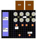
Chassis layout
Pictured below is how I've finally decided to assemble the amplifier into the 17" X 14" X 5" Hammond steel chassis that I've got.
Both amplifier channels are confined to the right most 11" X 17" of the chassis, separate from the power supply components To ensure adequate cooling the 807's are spaced 3" from each other at the rear of the chassis and the output transformers are bolted directly behind on the rear panel.
This will allow me to keep all the point-point wiring of the output stages short and neat.
The four 12AT7 cathode follower drivers are horizontally in-line roughly at the centre of the chassis and the two 12AX7 cathode follower input buffers are towards the front.
The sockets for these six valves as well and entire amplifier circuit besides the 807 PPP output stage are mounted on two large 5" X 7" PCB's mounted under the chassis (shown by the blue outline).
All the power supply circuitry will be mounted at the left most 6" X 17" of chassis, partitioned from the amplifier half with an aluminium plate.
A pair of 300VA Toroidal power transformers for the plate and screen supply voltages will be mounted with the aid of a fabricated bracket on the top of the chassis, standing upright along the left hand side.
These transformers will be enclosed in a fabricated 2.5”W X 12”D X 5”H rectangular aluminium box.
The heater transformers and auxiliary supply transformers will all be mount out of sight underneath the chassis.
Cheers,
Glen
Attachments
- Status
- Not open for further replies.
- Home
- Amplifiers
- Tubes / Valves
- 811a Opt