Hi
According the Aikido blog0067 here : http://www.tubecad.com/2006/06/blog0067.htm, I'm interested in building a low-volage Aikido version with buffer. This will be my headphone amp project, and there are some points I woud like to understand.
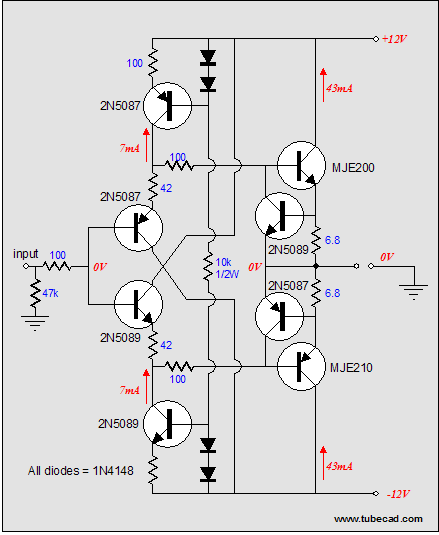
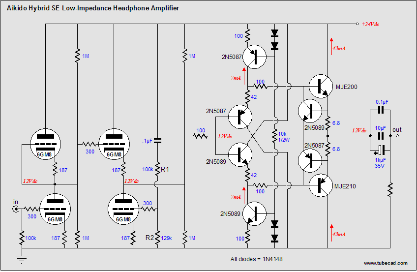
In the first schematic, it is only the solid state buffer. Right? It has R 47K at the input. Then comes to the second schematic which is the combination of the low-voltage AIKIDO and the solid state buffer. In this second schematic, this 47K was removed. What happen if we keep the 47K resistor?
I asked this question because I separated the low-voltage AIKIDO and the solid state buffer to two PCBs. One PCB is for Aikido. The other one is for the solid state buffer which includes R47K.
Many Thanks!!!
According the Aikido blog0067 here : http://www.tubecad.com/2006/06/blog0067.htm, I'm interested in building a low-volage Aikido version with buffer. This will be my headphone amp project, and there are some points I woud like to understand.
In the first schematic, it is only the solid state buffer. Right? It has R 47K at the input. Then comes to the second schematic which is the combination of the low-voltage AIKIDO and the solid state buffer. In this second schematic, this 47K was removed. What happen if we keep the 47K resistor?
I asked this question because I separated the low-voltage AIKIDO and the solid state buffer to two PCBs. One PCB is for Aikido. The other one is for the solid state buffer which includes R47K.
Many Thanks!!!
The 47K isn't required because the low voltage aikido output stage provides a path for the transistor base current. The resistor also creates an additional ac and dc load on the output of the aikido circuit, which given the low operating voltages and currents may result in increased distortion. (Conjecture on my part as I have neither built nor analyzed the performance of this circuit.)
One other comment - I have used a very similar buffer circuit, and I would recommend placing the 100 ohm base resistors very close to the output transistors. (MJE200/210) Note that the transistors connected across the 6.8 ohm emitter resistors in the output stage are to provide short circuit protection, and I think in an application like this can be safely omitted.
One other comment - I have used a very similar buffer circuit, and I would recommend placing the 100 ohm base resistors very close to the output transistors. (MJE200/210) Note that the transistors connected across the 6.8 ohm emitter resistors in the output stage are to provide short circuit protection, and I think in an application like this can be safely omitted.
Thank a lot Kevin!!!!
- If I use the solid-state buffer for other schematics (not for Aikido)? do we need R47K?
- May I know the reason why we need to place R100 close to MJE200/210 as much as possible?
- If I use the solid-state buffer for other schematics (not for Aikido)? do we need R47K?
- May I know the reason why we need to place R100 close to MJE200/210 as much as possible?
- Status
- Not open for further replies.