I bought a abandoned project that was 80% complete.
Some capacitors was missing and the ccs and mosfet circuit was not finished .
I found some of the obsolete parts but not the Mosfets. But i read on this forum that you could use 2 different types.
2SK3564 or FDPF5N60.
I bought both. So witch one should i use?
Second question:
The power transformer i got are from a chinese 300b SE amp. It was wired with a separate heater winding for each 300b tube. So im thinking on cutting the traces on the SE pcb to one of the tubes and make a secondary rectifing circuit on a small protoboard for the other tube. So what parts do i need to get that up and Running? And where to cut? 🙂. I have 2 x PQ5EV5 🙂
Use the FDPF5N60 mosfet as it has a lower Crss capacitance.
We need more information about the power transformer that you have, as it may not be suitable for use with a TSE.
Many low budget 300B amps use cathode bias for the 300B tubes. A large resistor from the filament winding to ground will be present if this is the case. Here the B+ voltage will be in the 450 volt or more range which is too high for a fixed bias amp. You will need to measure the AC voltage on the high voltage winding before using this transformer with a TSE which runs a B+ of 360 to 400 volts.
The HV winding must be Center Tapped 600 to 660 volts. A non CT 300 to 330 volt winding with a bridge rectifier will not provide negative voltage for bias and mosfet power.
This amp possibly also used AC heating on the 300B tubes. In this case the filament windings deliver 5.0 volts. The TSE uses regulated DC for the filaments to provide far better line frequency IMD performance. The regulator needs between 6 and 7 volts of clean DC to work correctly. It is not possible to get 6+ volts of clean DC from a 5.0 volt winding, a 6.3 volt winding of at least 4 amps is needed.
If the 6.3 volt winding in your transformer only powered the driver tubes it probably does not have enough current capability to run two driver tubes AND two 300B's.
If the HV winding on your transformer is somewhere around 600 to 660 VCT it can be used for HV. You could then build the board as is and use another 6.3V 4A transformer for the filament power. The CT is not needed on the 6.3V winding for a 300B build.
You will also need a 5 volt winding for the 5AR4. If the old amp used silicon rectifiers, you could parallel both 5 volt windings for the rectifier tube.
Last edited:

")
Thoughts anyone?
What is your wall power? I see this power transformer expects 110 Vac to deliver the specified voltages. It could work with some adjustments in B+ voltage. Current capability is probably good for your rebuild application.
Your build is coming along nicely. Good luck!
You may want to keep an eye on the voltages you get from the transformer with 230Vac wall power in stead of design 220Vac. In the US our power is specified at 117Vac, but I often measure 126Vac at my home.
I checked the wall power today when i was working on another amp build i powered with my variac. The wall power at my workbench is 237Vac So yes i will use a variac and keep a close eye on the voltages when i fire it up for the first time
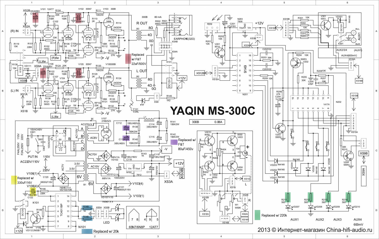
I own a Yaqin MS-300C. Did you get any other parts in addition to the power transformer?
I think it will be a good fit for the tubelab SE board.
It uses grid bias. The power transformer has a separate winding for the bias voltage.
The 300B filaments receive rectified DC from the 6Volt winding. It is 6 volts to compensate for the diode voltage drop when rectifying it.
Your wall voltage is high and you may need to add some dropping resistors in the filament supplies and the B+ to get the voltage down. In theory the filament supplies will be in an acceptable range but dropping resistors are cheap.
Steve
I think a challenge with this amp is to plan the chassis for it. How do you intend to present it at the end?
Unfortunately I keep getting delayed during my build - now I am stuck overseas for some months, but this was what I was attempting before that. I kept the UX4 sockets on short leads and attached them to the top plate, and the rectifier is also on leads and moved more to one side. The goal was a symetrical top plate, and keep access to do the adjustments when everything was assembled.


Unfortunately I keep getting delayed during my build - now I am stuck overseas for some months, but this was what I was attempting before that. I kept the UX4 sockets on short leads and attached them to the top plate, and the rectifier is also on leads and moved more to one side. The goal was a symetrical top plate, and keep access to do the adjustments when everything was assembled.
- Home
- More Vendors...
- Tubelab
- Finishing a old abandoned SE amp. Some modefication questions etc.