I recently bought a new toy. My very first oscilloscope.
Today I attached dummy loads to my SSE speaker terminals and ran some tests. Just playing around and learning how to use the o-scope.
I decided to measure output power with different rectifiers, output tubes, triode vs. UL, etc.
Mostly I got the results that I expected regarding output power.
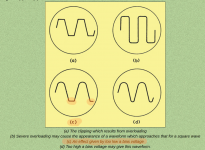
One thing I noticed is that the bottom of the waves were starting to clip quite a bit before the top of the waves clipped. This happened regardless of other factors mentioned.
Based on the diagram and explanation (attached) it seems that my bias voltage needs to be higher? Does this mean I should increase my cathode bias resistor value (which should reduce cathode current but increase voltage)?
I am trying to understand the balancing act going on here. It seems like if I can shift the whole wave up, to a point where the top and bottom of the wave start to clip at the same time, that would be ideal. Maybe I don't understand it?
Today I attached dummy loads to my SSE speaker terminals and ran some tests. Just playing around and learning how to use the o-scope.
I decided to measure output power with different rectifiers, output tubes, triode vs. UL, etc.
Mostly I got the results that I expected regarding output power.
One thing I noticed is that the bottom of the waves were starting to clip quite a bit before the top of the waves clipped. This happened regardless of other factors mentioned.
Based on the diagram and explanation (attached) it seems that my bias voltage needs to be higher? Does this mean I should increase my cathode bias resistor value (which should reduce cathode current but increase voltage)?
I am trying to understand the balancing act going on here. It seems like if I can shift the whole wave up, to a point where the top and bottom of the wave start to clip at the same time, that would be ideal. Maybe I don't understand it?
Attachments
Last edited:
Thanks Win. Your second point did occur to me and I suppose if I really wanted to I could probe the appropriate spot on the SSE to look at the output of the driver stage. Just knowing that this is likely an inherent characteristic of SE amps is good enough for me at this point.
... probe the appropriate spot on the SSE to look at the output of the driver stage ...
I prefer the control grid of the power tube, because the DC from the preceding stage is blocked by the coupling cap. Or should be .... If it is clipping there, then proceed back.
The CCS loaded 12AT7 can swing a *lot* of volts before it clips. I fooled around with measuring it, using the AC VTVM in my AA-1 right after I built it ( the AA-1). I doubt the front end would ever be the source of clipping in an SSE, unless the SSE is running somewhere less than 225 - 230 volts overall B+.
I still have those measurements in my notebook if anyone is interested. I'm always dubious about my measurement techniques and the validity of my results due to my inexperience, and would not mind seeing what someone else measured as a cross check. I used 600 ohms as the load for the 12AT7 and a 1100 Hz test sine.
My understanding is with S.E. both sides of the waveform should clip evenly (as evenly as you can get it anyway). Your bias is too low. You want both sides to look the same (both slightly clipping). Try a lower valued cathode resistor which will up the current in the tube and see if the sine wave changes to a more even result.
Hi Andrew,
My experience with cathode bias resistor adjustment is very limited, but the results have been that reducing the resistor value increases current, but reduces voltage. Conversely, increasing the resistor value decreases current but increases voltage.
I admit I don't understand tube amps very well (and electronics in general) but I think this is correct. No?
One way to find out is to try both increasing and decreasing the cathode bias resistors and comparing the outcomes. I can easily swap the resistors in and out so that's what I'll do. I'll start with decreasing the value.
"...but the results have been that reducing the resistor value increases current, but reduces voltage. Conversely, increasing the resistor value decreases current but increases voltage."
Correct.
If you look at George's page here
Tubes and Applications | Tubelab
you can see the relationship in the table he provided from TubeCad.
I should add that when doing the bias adjustment you should be at full power output.
Remember also that there is a relationship between all the tube elements, so as you adjust one, others will also change.
Remember Ohms Law
V
______
I X R
Hi Andrew,
Yes, I studied George's SSE pages thoroughly and noticed that pattern before I even built my SSE. My limited experimenting and measurements match that pattern.
So back to the original point about the screenshot - it states "An effect given by a too low bias voltage". The way I interpret this is that I need to increase bias voltage. The only way I know how to do that is to adjust the cathode bias resistor, but it seems to me the value should be increased, not reduced.
Ideally, I can learn/understand how this all works together. However, I think I will stick with the plan and simply swap in different values, perform tests, and take notes.
Maybe George will have something to say about it?")
Yes, I studied George's SSE pages thoroughly and noticed that pattern before I even built my SSE. My limited experimenting and measurements match that pattern.
So back to the original point about the screenshot - it states "An effect given by a too low bias voltage". The way I interpret this is that I need to increase bias voltage. The only way I know how to do that is to adjust the cathode bias resistor, but it seems to me the value should be increased, not reduced.
Ideally, I can learn/understand how this all works together. However, I think I will stick with the plan and simply swap in different values, perform tests, and take notes.
Maybe George will have something to say about it?
But the comment in the screenshot says nothing about current. It says my cathode voltage is too low. So don't I need to increase the cathode voltage? Decreasing the resistance will increase current and reduce voltage. The opposite of what I want (according to that screenshot).
Last edited:
Yes, you are running out of power supply, and also observing one of the characteristics, some might say limitations, of cathode ( automatic ) bias.
If you want to play around with bias voltage, it's best to have a fixed bias amplifier, and a variable negative voltage bias power supply. It doesn't take much of a power supply as it only needs to supply a few milliamps, but you still have to have a B+ power supply that can supply the necessary current.
At some point you always either run out of power supply, or run out of tube.
I just don't recall ever seeing one of my single ended amps clip symmetrically, even a little single ended RF power amp I built as part of another project, clipped only one part of the wave in one of its first iterations.
I would certainly be interested in learning more about this subject.
OK, when all else fails, RTFM.
Sadly, I have a brief to write so I can't, but I did find this explanation which I've attached as .pdf's. Look at the bottom of page 125 to the diagram on the next page. I have a .pdf of the whole book, so it is likely available for download online.
I thought I had a download of the Radiotron Designers Handbook, but I can't find it on my computer. I have a hard copy of the 4th edition at the lake and will probably be back up there this weekend, so I might take a look at it.
Cogitech, now that I think about it, when you run SE Amp CAD, my recollection is that when drive exceeds the grid voltage, it will give a recommendation to lower the drive, or change the bias. So you might want to play with SE Amp CAD some.
Attachments
Last edited:
If you plot your operating point and load line on a triode's characteristic curves graph, you can see its output as you change the input. The unequal spacing of the curves will result in 2nd order harmonic distortion. You can also see that a low bias voltage will result in cutoff as the input signal reaches the bias level.
After some playing in SEAmpCAD, it is become clear to me that this has more to do with the relative voltages of the grid (Vg) and the cathode (Vk). As Vin is increased, Vg(min) increases (becomes less negative). As Vg min becomes positive relative to Vk, things start to go wonky. At some point it all goes to poop.
However, even under "normal" operating conditions the asymmetry of the waveform is there (the voltage swings into the negative more than the positive), and changing the cathode bias resistor does very little to change it (in the simulation). As Vin is increased, the asymmetry of the voltage swing seems to grow exponentially.
However, even under "normal" operating conditions the asymmetry of the waveform is there (the voltage swings into the negative more than the positive), and changing the cathode bias resistor does very little to change it (in the simulation). As Vin is increased, the asymmetry of the voltage swing seems to grow exponentially.
Last edited:
- Status
- This old topic is closed. If you want to reopen this topic, contact a moderator using the "Report Post" button.
- Home
- More Vendors...
- Tubelab
- Bias Question