Hey everyone, I'm embarking on this journey for the first time. Would appreciate some help with the parts list just to make sure everything I got on here will work correctly. I used the list from the website along with a list from another user to put this together. I have done DIY speakers and crossovers but never an amplifier.
My main questions are:
1. Is everything for the PC board compatible/correct?
2. Is the internal wire beefy enough at 20ga?
3. Will the Hammon chassis be strong enough to support all the transformers, choke, etc, without bowing?
Interested to year your thoughts. Thanks in advance!
My main questions are:
1. Is everything for the PC board compatible/correct?
2. Is the internal wire beefy enough at 20ga?
3. Will the Hammon chassis be strong enough to support all the transformers, choke, etc, without bowing?
Interested to year your thoughts. Thanks in advance!
Attachments
3. Will the Hammon chassis be strong enough to support all the transformers, choke, etc, without bowing?
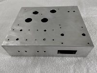
Yes. I used the Hammond aluminum 1444-12103 (12" x 10" x 3") and it's very sturdy - even with the gigantic Edcor XPWR035 power transformer! Whatever chassis you choose, take your time doing your layout; there are lots of holes to properly align (twice) and drill (once).
Attachments
I did not see diodes D3 and D4 on your parts list.
I only see D1 and D2 on the official list, am I missing where they are? What diodes go there and what is their function?
Parts List | Tubelab
The parts list on the Tubelab site was not updated for the current PCB revision. D3 and D4 were added along with TR1 to help make life easier for the rectifier tube.
Starting a SSE build
Starting a SSE build
The parts list on the Tubelab site was not updated for the current PCB revision. D3 and D4 were added along with TR1 to help make life easier for the rectifier tube.
Starting a SSE build
Ahh ok great thanks for the link!
Ahh ok great thanks for the link!
No problem. I made the same oversight in my build (along with a host of other mistakes) so I am happy to have saved someone else from the same trouble. 🙂
One other note. You might want to consider getting a few different values for R17 and R27 depending on what tubes you plan to use. Look at the chart on the Tubelab website and search here for likely options.
Last edited:
If it helps I posted the parts list I used in my build thread.
Oh yeah another SSE build
For wiring I purchased some 18g wire rated for 600v to use for any high voltage internal hookup. You may not need any extra wire though as the transformers come with long leads and trimming to fit will leave some extra. For the line level inputs I used some 28g copper wire pulled from Cat6 cables for short connections and some shielded Mogami W2330 Interconnect Wire to run front to back. p { margin-bottom: 0.1in; line-height: 115%; background: transparent }
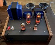
This was my first tube amp build as well and I am very pleased with the results. It's very doable just keep safety at the top of the list 🙂
Oh yeah another SSE build
For wiring I purchased some 18g wire rated for 600v to use for any high voltage internal hookup. You may not need any extra wire though as the transformers come with long leads and trimming to fit will leave some extra. For the line level inputs I used some 28g copper wire pulled from Cat6 cables for short connections and some shielded Mogami W2330 Interconnect Wire to run front to back. p { margin-bottom: 0.1in; line-height: 115%; background: transparent }
This was my first tube amp build as well and I am very pleased with the results. It's very doable just keep safety at the top of the list 🙂
birkbott,
I am using a tube rectifier (Sovtek 5AR4) so I did not install D1 and D2.
I did install the two 1N4007 diodes in D3 and D4. I also installed the CL-140 inrush limiter in TR1. These parts ease the power-on hit to the tube rectifier.
These are the three parts that I believe are not in the Tubelab SSE parts list. They are common parts and can be purchased from Mouser or Digikey.
Other than those three parts I followed the Tubelab SSE parts list to the letter.
So, if you are using a tube rectifier don't buy D1 and D2 and do add D3, D4, and TR1 to your parts list.
I hope this helps.
Attachments

birkbott,
I am using a tube rectifier (Sovtek 5AR4) so I did not install D1 and D2.
I did install the two 1N4007 diodes in D3 and D4. I also installed the CL-140 inrush limiter in TR1. These parts ease the power-on hit to the tube rectifier.
These are the three parts that I believe are not in the Tubelab SSE parts list. They are common parts and can be purchased from Mouser or Digikey.
Other than those three parts I followed the Tubelab SSE parts list to the letter.
So, if you are using a tube rectifier don't buy D1 and D2 and do add D3, D4, and TR1 to your parts list.
I hope this helps.
Thanks, this is where I get mixed up though, if I search for 1N4007 it’s not available, but 1N4007-T is and 1N4007-E3/E4 and many other variations are. Are those the same thing?
I used Mouser part #
863-1N4007RLG 1N4007RLG
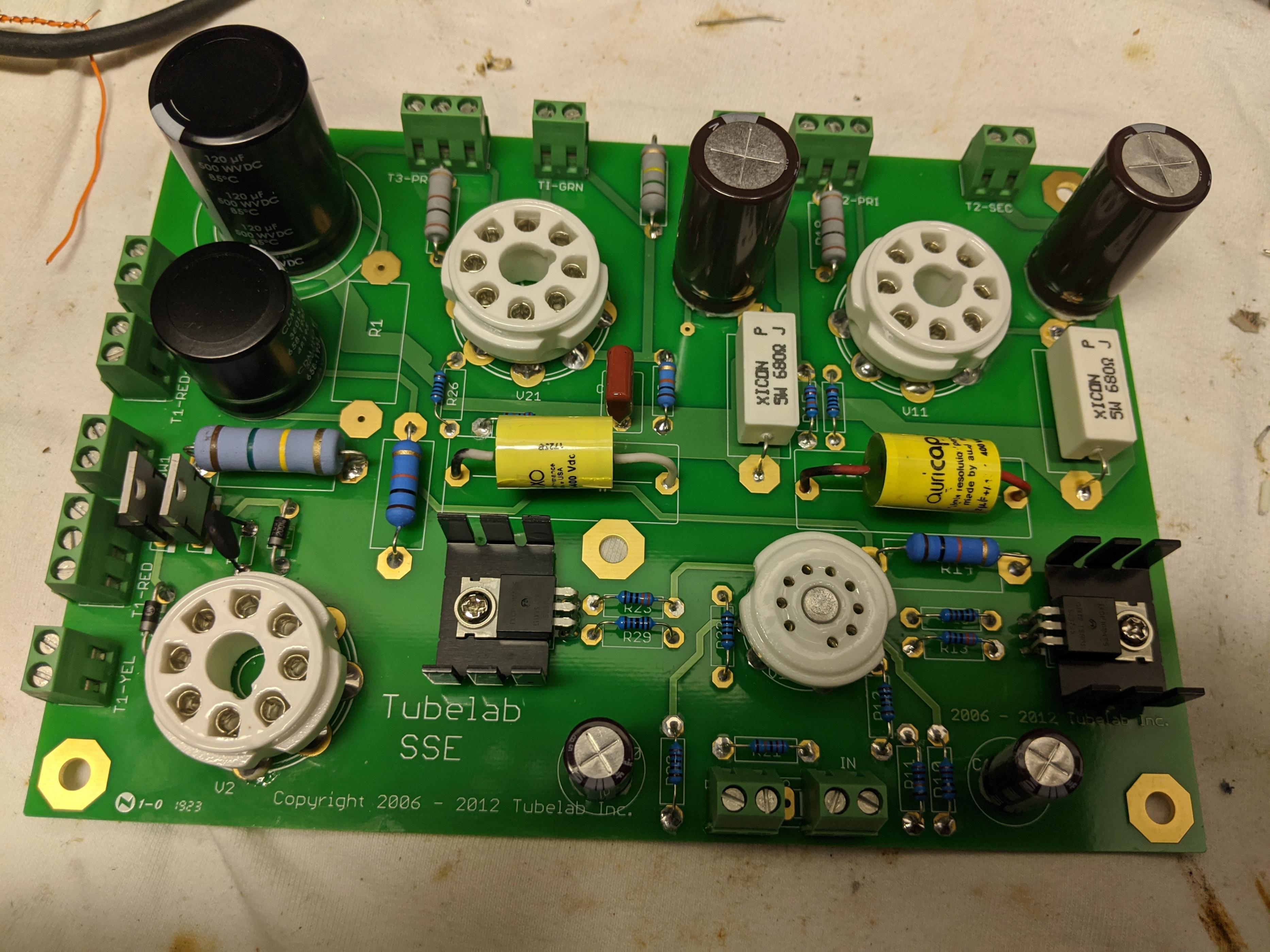
I built and tested my board with both tube and solid state rectification so all parts are present. Mine is with all parts on top.
863-1N4007RLG 1N4007RLG
I built and tested my board with both tube and solid state rectification so all parts are present. Mine is with all parts on top.
Last edited:
I used Mouser part #
863-1N4007RLG 1N4007RLG
Thanks, I really do appreciate the help!
Thanks everyone for your help and for all the information in this thread and elsewhere. I am going back and making some changes to my parts list, and I am stuck on the Cathode Bias Resistor.
It says I should use the transformers to determine my B+ voltage and then use the tables on the site to determine which resistance to get but I'm not sure exactly how to do that.
I'm planning on the Edcor XPWR035 Power and CXSE25-8-5K OP transformers and to use KT-88 Tubes.
It says I should use the transformers to determine my B+ voltage and then use the tables on the site to determine which resistance to get but I'm not sure exactly how to do that.
I'm planning on the Edcor XPWR035 Power and CXSE25-8-5K OP transformers and to use KT-88 Tubes.
With the Edcor XPWR035 you want to use the 450V B+ section of George's chart, and you have a 5K output transformer.
So, look at the section for KT88 - 450 - 5000: here:
Tubes and Applications | Tubelab
The KT88 has a max plate dissipation of 42 watts. The higher the cathode resistor value the lower your plate dissipation. Using 470 Ohm resistors should put you around 33 watts. That's on the cooler, safe side. Using 390 Ohm resistors raises the plate dissipation to around 38 watts.
At any rate, use the Xicon wire wound 5W type. I would start with this part:
https://www.mouser.com/ProductDetail/Xicon/280-CR5-470-RC?qs=Rk6YzfsJF03hhgRh0nkL9Q==
They're cheap enough, so buy some of these, too:
https://www.mouser.com/ProductDetail/Xicon/280-CR5-390-RC?qs=M3j1PW%2Bw%2BBalPAmy3MJGWA==
That way you can try both.
With the Edcor XPWR035 you want to use the 450V B+ section of George's chart, and you have a 5K output transformer.
So, look at the section for KT88 - 450 - 5000: here:
Tubes and Applications | Tubelab
The KT88 has a max plate dissipation of 42 watts. The higher the cathode resistor value the lower your plate dissipation. Using 470 Ohm resistors should put you around 33 watts. That's on the cooler, safe side. Using 390 Ohm resistors raises the plate dissipation to around 38 watts.
At any rate, use the Xicon wire wound 5W type. I would start with this part:
https://www.mouser.com/ProductDetail/Xicon/280-CR5-470-RC?qs=Rk6YzfsJF03hhgRh0nkL9Q==
They're cheap enough, so buy some of these, too:
https://www.mouser.com/ProductDetail/Xicon/280-CR5-390-RC?qs=M3j1PW%2Bw%2BBalPAmy3MJGWA==
That way you can try both.
This is great, thanks. I am fine with the safe zone but like you said I'll get both and see how it goes.
How did you get 450v from the specs on the Edcor?
Ok so I went through and updated my parts list. I will wait to order extra wire and the chassis until I get the PCB assembled and get the general layout so I know how much I'll need to order and how big the chassis will be. I intend to do 2 sided mounting so the tubes, transformers, supplemental cap and edcor choke will all show on top.
I added 2 different values for R17/27 and tried to keep the manufacturers the same as much as possible but not sure if that makes much of a difference.
I have a question about switches, the main ON/OFF I understand but I notice others have use the ON/ON switches for the Triode/UL, CFB and SS/Tube rectifier switches. How are those wired? How will I know which position equals which thing?
Anyhow, any other eyes on the parts list would be welcomed before I place all my orders.
Attachments
...
I have a question about switches, the main ON/OFF I understand but I notice others have use the ON/ON switches for the Triode/UL, CFB and SS/Tube rectifier switches. How are those wired? How will I know which position equals which thing?...
First you should study the wiring diagrams on the Tubelab website. Read through how to hookup Triode then UL without the switch, then do the same for CFB. You will see what the difference is between wiring each mode then when you look at the wiring diagram with the switches it should make sense.
George recommends getting the amp working in basic Triode mode first before adding any switches etc so that is something to keep in mind.
Since you are only planning to run the tube rectifier you don't need to install the switch for SS vs Tube but if you do this can be an on/off switch or if you use an on/on then one on position will just be open.
George recommends getting the amp working in basic Triode mode first before adding any switches etc so that is something to keep in mind.
Yes. I think people who have a lot of experience with this stuff - definitely not me - will tell you it's much easier to add a feature to a working amp than it is to troubleshoot an amp with the extras already added on.
Build the basic simple version first and get it working right.
- Home
- More Vendors...
- Tubelab
- SSE Parts List Help