Hi all, sorry for another thread about grounding, I have a layout that’s not like any other I’ve seen here so wanted to double check a few things.
So my plan is to use the output transformer bolt as a star ground (S), then ground the board via the RCA. Do both channels need to be ground¿ there is only one on the official diagrams.
Also, I have three sets of input jacks, all mounted to the chassis and insulated from the chassis by the plastic washers.
The other two (A,B,C and D) are for me to fashion an
‘Input selector’ by plugging in and out rca patch cables, like an old synthesiser.
Do I have to ground them in the same manner, to the star ground¿…
Also the switches for power, UL / feedback and volume all contact the chassis, should I ground them separately or will the fact that they contact the chassis suffice¿
I have used Neutrik SpeakOn connectors to hook up the speakers, there are no exposed metal parts on these, i assume they don’t need to be ground¿
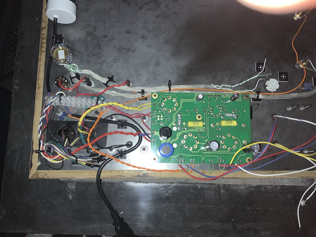
Finally, does anyone see a potential issue with the signal wires being so close to the power at the bottom of the image¿ I’ve shielded them just in case
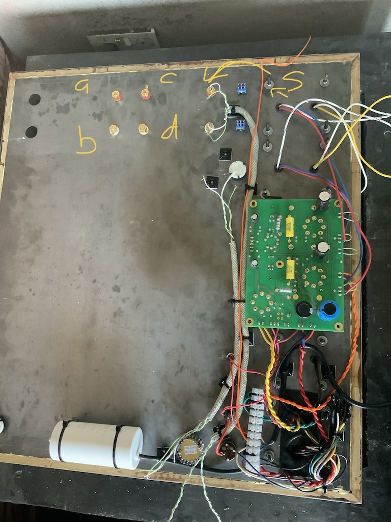
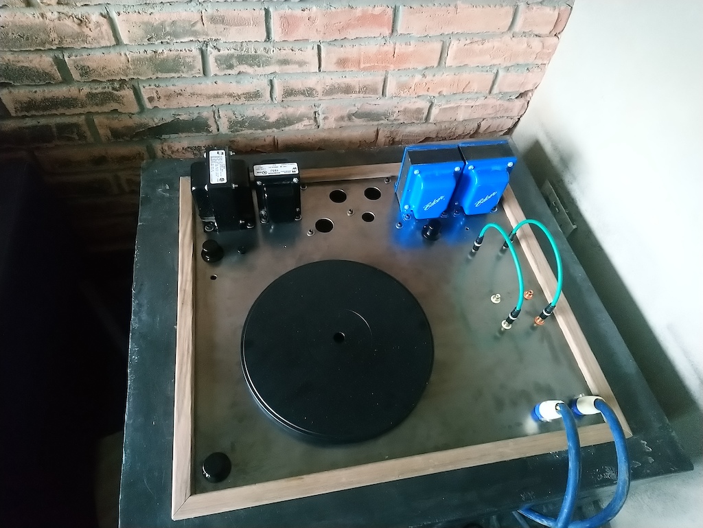
Here is the top side, I’ll be housing my turntable here as well. The two green cables will allow selection between phono pre amp and a wired connection from my computer. The two holes for switches above are UL and feedback. I’ll hook these up after I power the amp up and test it.
So my plan is to use the output transformer bolt as a star ground (S), then ground the board via the RCA. Do both channels need to be ground¿ there is only one on the official diagrams.
Also, I have three sets of input jacks, all mounted to the chassis and insulated from the chassis by the plastic washers.
The other two (A,B,C and D) are for me to fashion an
‘Input selector’ by plugging in and out rca patch cables, like an old synthesiser.
Do I have to ground them in the same manner, to the star ground¿…
Also the switches for power, UL / feedback and volume all contact the chassis, should I ground them separately or will the fact that they contact the chassis suffice¿
I have used Neutrik SpeakOn connectors to hook up the speakers, there are no exposed metal parts on these, i assume they don’t need to be ground¿
Finally, does anyone see a potential issue with the signal wires being so close to the power at the bottom of the image¿ I’ve shielded them just in case
Here is the top side, I’ll be housing my turntable here as well. The two green cables will allow selection between phono pre amp and a wired connection from my computer. The two holes for switches above are UL and feedback. I’ll hook these up after I power the amp up and test it.
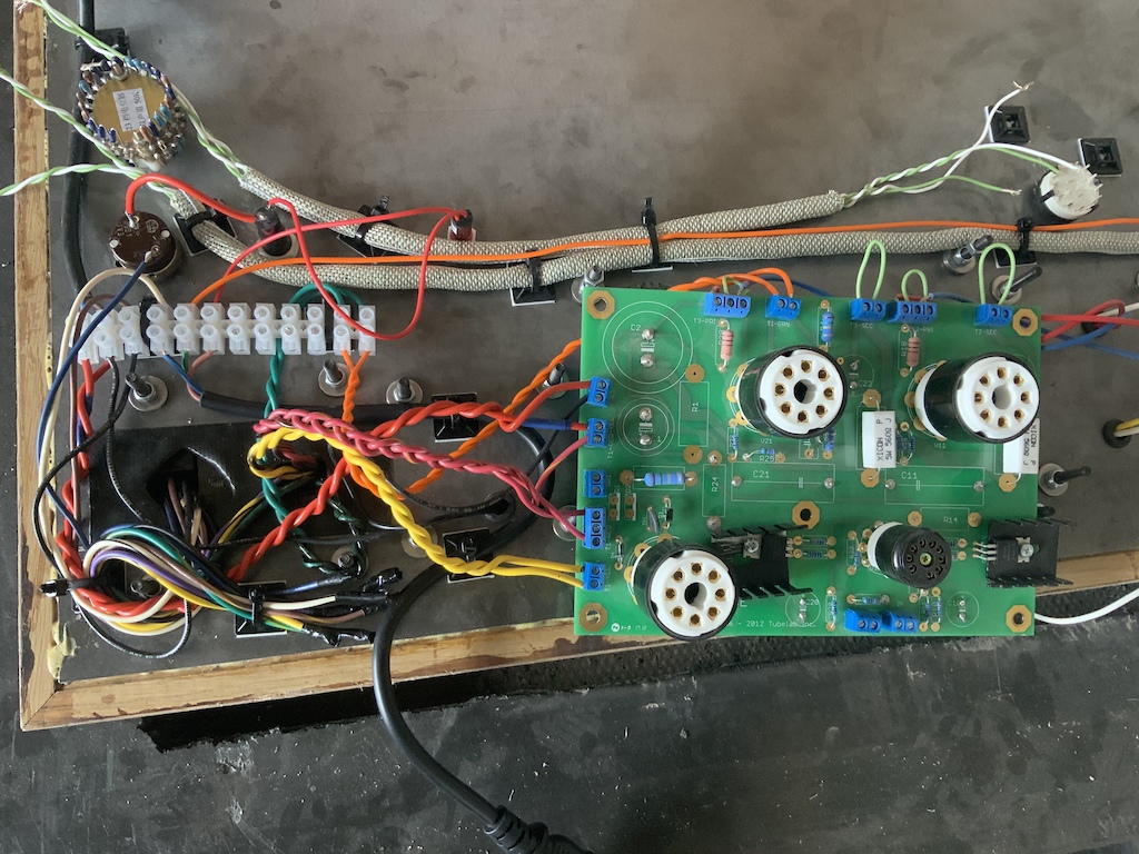
The output tube socket / extension in the upper right corner of your second picture appears to be installed incorrectly. The keyways should be at the same angle in both tubes. Please check this before powering up the amp.
It turns out the tube saver was defective, The Alignment tab on the bottom and the tab on top didn’t line up so even though it fitted in the octal tube socket the tube would always have been rotated round by one pin. I’ve ordered a replacement.
Does anyone have input on my grounding questions, before I fry myself
")
Last edited:
Also, I have three sets of input jacks, all mounted to the chassis and insulated from the chassis by the plastic washers.
The other two (A,B,C and D) are for me to fashion an
‘Input selector’ by plugging in and out rca patch cables, like an old synthesiser.
Do I have to ground them in the same manner, to the star ground¿…
Also the switches for power, UL / feedback and volume all contact the chassis, should I ground them separately or will the fact that they contact the chassis suffice¿
First off, the IEC ground should be securely connected to the chassis for safety and no other connections should be made here. The star ground, or 0 volt ground, should only connect to the chassis at only one point, preferably close to the IEC/chassis ground connection (close to the input if possible).
If I understand on what you want to do correctly, then connect all the RCA input signal GND together, then connect a single wire, preferably the input close to the star ground, and connect the GND from there to the star ground. By doing so, you will trap any ground loop in the input area. The inputs (all the R and all the L) can be connected to each other if you are going to use one pair of input at a time, then connect it the respective input on the board for R and L. Connecting the input signal and GND this way minimizes the magnetic coupling loop.
In my opinion, for the switches, chassis ground will do except for the volume control. The volume control GND should be part of the "signal" ground, not the chassis ground as it may result to a ground loop.
You might want to check this out http://hifisonix.com/wordpress/wp-content/uploads/2019/02/Ground-Loops.pdf
Pay attention to "loop areas" and difference between audio signal ground and AC safety ground. Hope this helps.
Last edited:
Also, I have three sets of input jacks, all mounted to the chassis and insulated from the chassis by the plastic washers.
The other two (A,B,C and D) are for me to fashion an
‘Input selector’ by plugging in and out rca patch cables, like an old synthesiser.
Do I have to ground them in the same manner, to the star ground¿…
Also the switches for power, UL / feedback and volume all contact the chassis, should I ground them separately or will the fact that they contact the chassis suffice¿
First off, the IEC ground should be securely connected to the chassis for safety and no other connections should be made here. The star ground, or 0 volt ground, should only connect to the chassis at only one point, preferably close to the IEC/chassis ground connection (close to the input if possible).
If I understand on what you want to do correctly, then connect all the RCA input signal GND together, then connect a single wire, preferably the input close to the star ground, and connect the GND from there to the star ground. By doing so, you will trap any ground loop in the input area. The inputs (all the R and all the L) can be connected to each other if you are going to use one pair of input at a time, then connect it the respective input on the board for R and L. Connecting the input signal and GND this way minimizes the magnetic coupling loop.
In my opinion, for the switches, chassis ground will do except for the volume control. The volume control GND should be part of the "signal" ground, not the chassis ground as it may result to a ground loop.
You might want to check this out http://hifisonix.com/wordpress/wp-content/uploads/2019/02/Ground-Loops.pdf
Pay attention to "loop areas" and difference between audio signal ground and AC safety ground. Hope this helps.
Thank you Amandarae, that was very helpful.
So I have wired the RCA’s in as shown, and moved the star ground to one of the input transformer bolts (top left bolt, at the end of the black IEC cable).
All RCA’s are insulated from the chassis. The RCA with the ground connection and the IEC are then connected to the star ground, which of course also contacts the chassis.
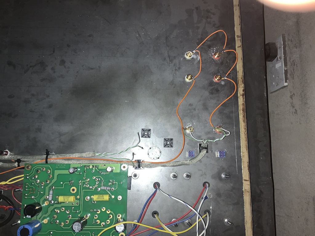
Is this what you meant¿
That will work. But if you experience a hum, this is what I am going to do.
2nd pic: I will connect the wire (long Orange wire) from the RCA input GND to the GND (0 Volt)from the amplifier board instead of the ground point of the IEC (the IEC connection to the chassis should be secure and no other connection should be made here, remember?).
Then, if you choose to do so, I will connect a wire from the board GND to a point on a chassis directly (preferably close to the input). You can do this easily by connecting the farthest end of the RCA string GND to the chassis right there where it is at.
- Status
- This old topic is closed. If you want to reopen this topic, contact a moderator using the "Report Post" button.
- Home
- More Vendors...
- Tubelab
- SSE grounding and general spot check