I hope everyone's well,
So, I'm reading that Norman H. Crowhurst piece, "Making Use of Load Lines," in an attempt to learn something on my own.
He states that one establishes the two points for a load line by determining B+ voltage and dividing it by the value of the plate resistor to find the plate current. Clear enough.
When I look at the SSE schematic, I'm not seeing a resistor connected to the power tube plate. Which resistor, or, rather, what resistance value do I read off of the schematic in order to calculate a load line?
It's funny, but I always feel like I need to apologize for asking these very basic questions. But, the answer isn't obvious to me, and I know no other way to learn than to research, read, and then ask questions.
Thanks!
David
Attachments
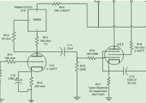
The output (power) tube feeds directly into the OPT.
The builder has the option to choose an OPT that works with whatever tube they choose. Common values range from about 3000 ohms for a KT88, to 8000 ohms for a 6V6GT. I use 5000 ohms for most of my amps.
Pick a common tube EL34, 6L6GC or KT88 and start with a 5000 ohm load line. You can play with the load and see that in an SE amp a lower load impedance gives more power, but more distortion, and a higher output impedance. A higher load impedance reduces the power output a bit, but lowers distortion and output impedance.
Here's everything you always wanted to know about load lines.
http://www.tubebooks.org/Books/Preisman_graph.pdf
http://www.tubebooks.org/Books/Preisman_graph.pdf
Here's everything you always wanted to know about load lines.
http://www.tubebooks.org/Books/Preisman_graph.pdf
Thanks! Looks like another good read.
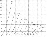
One other question, is there an online depository for load line charts for various tubes? I guess that's what you call them; the graphs with the grid voltage lines like the one pictured below.
After over an hour of Googling with numerous search terms I've come up empty handed. Maybe I'm not using the correct term for these charts.
Even better, is there a software program available? Other than SE Amp CAD which apparently won't run on my Windowds 10 PC.
Thanks!
After over an hour of Googling with numerous search terms I've come up empty handed. Maybe I'm not using the correct term for these charts.
Even better, is there a software program available? Other than SE Amp CAD which apparently won't run on my Windowds 10 PC.
Thanks!
Attachments
You probably have already seen this
Triode / Pentode Loadline Simulator v.1.0 (20161216 www.trioda.com)
Triode/Pentode Loadline Calculator
For Data sheets I usually go here
Frank's electron Tube Data sheets
Triode / Pentode Loadline Simulator v.1.0 (20161216 www.trioda.com)
Triode/Pentode Loadline Calculator
For Data sheets I usually go here
Frank's electron Tube Data sheets
Other than SE Amp CAD which apparently won't run on my Windowds 10 PC.
I ran SE Amp CAD on a W10 PC a couple years ago when a forum post asked about my 845 SE simulation, so I just tried it, and got the same ugly blue box that you probably got.....thanks M$ for killing more of my software.
Tubelab will cease to exist when my 10 year old pro version of Eagle PCB no longer works. I can't afford Autodesk's $600 per year extortion plan.....but I am keeping a W7 PC alive just in case.
The picture you showed is of the "plate curves" which are given in tube manuals and data sheets. For most pentodes, there are several different sets for various screen grid voltages. Choose the page that is closest to your intended screen voltage. Load lines are drawn on these curves.
As a pre teen kid I made guitar and HiFi amps out of parts salvaged from discarded radios and TV's. I had no clue what I was doing, but parts were free at the local county trash dump. I had some successes, but many failures. I never could understand why a big fat tube like the 6DQ6 would just glow red and make 1 or 2 watts, but the skinny 6BQ6 in the same socket rocked out 10 watts without an issue.....
At age 13 I got accepted into a 3 year electronics program at a technical high school where I would learn about bias, load lines and impedance matching. Those graph paper and slide rule (the pocket calculator wasn't invented yet) designs worked. My success rate went from maybe 5% to 90% or so...…..
Now 50 years and a 41 year engineering career later, I fully understand vacuum tubes and most modern tech, but I no longer draw load lines!
Today I use a simulation program called LT spice. There are models for most common vacuum tubes, and it is fairly accurate. It will tell you that a circuit will NOT work with a fairly high accuracy. If it says something will work, then it's usually worth breadboarding and testing. I will go back and forth between my real amp and the virtual amp tinkering with parts values until both agree, or come close. These experiences are also a good learning tool
LT spice will give you power output values that are pretty close. I just crank up the input level until the distortion hits 1% and read the output voltage. It will be pretty close to reality. The THD and input sensitivity may not be so accurate, but they are in the ballpark.
One can draw load line on paper, or one can put their amp topology into LT spice, and play with the OPT ratio so that you can try every possible impedance (up to your patience limit) without lifting a pencil. I just start high (12000 ohms or so) drop 1000 each time you rerun the sim, and write down the power, 2H, 3H and 5H. You should see a pattern so you know what OPT will work best.
LT spice is a free download from Linear Technology and it works fine on W10. There are tutorials on this forum, Linear's web site, and YouTube. There is a page of tube models on this forum too.
...but I am keeping a W7 PC alive just in case. ....
I keep my elderly HP Netbook in service with XP on it, just so I can run things like SE Amp CAD, Tube Cad, and some two way radio programming software that only runs on XP or even Win 3.1 ...
The computer in my radio room is loaded with XP for the same reason; been meaning to set it up for dual boot installation with XP on one side, and some flavor of Linux on the other.
Folks, there just really is no excuse for not running virtual machines.
Virtualbox is 100% free and is stable enough for enterprise deployments, IMO. Oracle VM VirtualBox
Download and in stall it on Windows 10 or whatever you are running and then create a new virtual machine and install whatever OS you want - in this case Windows XP. It is dead simple.
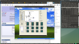
Screenshot of my desktop (Linux) attached. As you can see, there is an entire installation of XP running in that window. The only reason I have it is to run SE Amp CAD. On my 6 core system with SSD, it takes about 12 seconds to boot it and launch SE Amp CAD.
Virtualbox is 100% free and is stable enough for enterprise deployments, IMO. Oracle VM VirtualBox
Download and in stall it on Windows 10 or whatever you are running and then create a new virtual machine and install whatever OS you want - in this case Windows XP. It is dead simple.
Screenshot of my desktop (Linux) attached. As you can see, there is an entire installation of XP running in that window. The only reason I have it is to run SE Amp CAD. On my 6 core system with SSD, it takes about 12 seconds to boot it and launch SE Amp CAD.
Attachments
Thanks vernonb. Yes, I did see that one!
Thanks George. I installed LTSpice; I'll see if I can learn to use it. As you point out, there's a lifetime's worth of knowledge to acquire on this subject. It can be overwhelming. I'm just sort of taking a blind stab at something that appeared interesting and maybe within reach. For me, it's all about establishing a foothold, and expanding from there. I've tried reading electronics books. Atom theory bores me no end, and when the math starts cropping up, I put the books away.
I'm thinking that for my next project I'd like to try building something point-to-point, like a 5F1 Champ. Actually connecting physical components together into a circuit should make the relationships of parts more clear for me. A schematic is an abstraction comprised of symbols.
Thanks cogitech. I found this step-by-step guide to installing VirtualBox, and getting a free copy of XP. I might give it a try on my old laptop:
How to Get a Windows XP Download Free From Microsoft, Legally
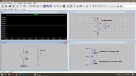
So, I've been messing around in LTspice. I discovered that there is no symbol for a potentiometer. You have to make your own model of one!
After two hours of trying to follow really bad Youtube videos that assume you already know LTspice, I finally got one to work.
I set the value at 50% and ran it with 10 volts. The result shows 5 volts! A small success.
After two hours of trying to follow really bad Youtube videos that assume you already know LTspice, I finally got one to work.
I set the value at 50% and ran it with 10 volts. The result shows 5 volts! A small success.
Attachments
I ran SE Amp CAD on a W10 PC a couple years ago when a forum post asked about my 845 SE simulation, so I just tried it, and got the same ugly blue box that you probably got.....thanks M$ for killing more of my software.
Tubelab will cease to exist when my 10 year old pro version of Eagle PCB no longer works. I can't afford Autodesk's $600 per year extortion plan.....but I am keeping a W7 PC alive just in case.
The picture you showed is of the "plate curves" which are given in tube manuals and data sheets. For most pentodes, there are several different sets for various screen grid voltages. Choose the page that is closest to your intended screen voltage. Load lines are drawn on these curves.
As a pre teen kid I made guitar and HiFi amps out of parts salvaged from discarded radios and TV's. I had no clue what I was doing, but parts were free at the local county trash dump. I had some successes, but many failures. I never could understand why a big fat tube like the 6DQ6 would just glow red and make 1 or 2 watts, but the skinny 6BQ6 in the same socket rocked out 10 watts without an issue.....
At age 13 I got accepted into a 3 year electronics program at a technical high school where I would learn about bias, load lines and impedance matching. Those graph paper and slide rule (the pocket calculator wasn't invented yet) designs worked. My success rate went from maybe 5% to 90% or so...…..
Now 50 years and a 41 year engineering career later, I fully understand vacuum tubes and most modern tech, but I no longer draw load lines!
Today I use a simulation program called LT spice. There are models for most common vacuum tubes, and it is fairly accurate. It will tell you that a circuit will NOT work with a fairly high accuracy. If it says something will work, then it's usually worth breadboarding and testing. I will go back and forth between my real amp and the virtual amp tinkering with parts values until both agree, or come close. These experiences are also a good learning tool
LT spice will give you power output values that are pretty close. I just crank up the input level until the distortion hits 1% and read the output voltage. It will be pretty close to reality. The THD and input sensitivity may not be so accurate, but they are in the ballpark.
One can draw load line on paper, or one can put their amp topology into LT spice, and play with the OPT ratio so that you can try every possible impedance (up to your patience limit) without lifting a pencil. I just start high (12000 ohms or so) drop 1000 each time you rerun the sim, and write down the power, 2H, 3H and 5H. You should see a pattern so you know what OPT will work best.
LT spice is a free download from Linear Technology and it works fine on W10. There are tutorials on this forum, Linear's web site, and YouTube. There is a page of tube models on this forum too.
Dear friend, hello, humbly ask you, what are the steps in LTSPICE?
“I just crank up the input level until the distortion hits 1% and read the output voltage.”
I will perform FFT analysis in LTSPICE, but I know where to calculate THD.
- Home
- More Vendors...
- Tubelab
- SSE Load Line Question