Hey all, I'm finally getting started on putting my SSE together and will be drilling some holes into my chassis this afternoon...I've started looking at the wiring diagrams (no CFB or UL for now) and have a few questions. Some may be totally basic, but I want to make sure I get it right.
parts I'm using:
Edcor XPRW035 PT
Edcor CXC 125-10H choke
Edcor CXSE25-8-5K OPT
Temco 370-400V 100uf Run Capacitor
1. Choke: is the choke directional? I have yellow & black wire..does it matter which one goes into L1: 01/02?
2. Motor Cap: which terminal is +? Do I need a high quality sliver wire, or will basic 18 or 20g wire work? the wiring diagram shows + into L1:01 and negative into Red-Yel:01
3. PT: Red/Black (370v center tap) into T1 Red-Yel: 02?
4. OPT: White is common. this goes to black speaker jack? Yellow to red jack? don't use the screen tap if I'm not using CFB right?
5. Input Jacks: just to confirm: center is input, outer is ground? would a higher quality wire for the chassis ground make a difference? or just a basic 18 or 20g wire work ok?
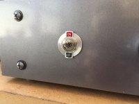
6. IEC input/fuse/switch: where is the best place to put the fuse? inline between the IEC & switch (my initial thought)? or in between PT & IEC? or in between PT and switch? does it matter how I wire the fuse holder (ie: is it directional)?
Hope this makes sense, I'll try and put a few pics up to help clarify.
Thanks,
-Jeff
parts I'm using:
Edcor XPRW035 PT
Edcor CXC 125-10H choke
Edcor CXSE25-8-5K OPT
Temco 370-400V 100uf Run Capacitor
1. Choke: is the choke directional? I have yellow & black wire..does it matter which one goes into L1: 01/02?
2. Motor Cap: which terminal is +? Do I need a high quality sliver wire, or will basic 18 or 20g wire work? the wiring diagram shows + into L1:01 and negative into Red-Yel:01
3. PT: Red/Black (370v center tap) into T1 Red-Yel: 02?
4. OPT: White is common. this goes to black speaker jack? Yellow to red jack? don't use the screen tap if I'm not using CFB right?
5. Input Jacks: just to confirm: center is input, outer is ground? would a higher quality wire for the chassis ground make a difference? or just a basic 18 or 20g wire work ok?
6. IEC input/fuse/switch: where is the best place to put the fuse? inline between the IEC & switch (my initial thought)? or in between PT & IEC? or in between PT and switch? does it matter how I wire the fuse holder (ie: is it directional)?
Hope this makes sense, I'll try and put a few pics up to help clarify.
Thanks,
-Jeff
Last edited:
Well haven't got a lot of responses, so may be some pics will help garner some interest. I finished the chassis and started wiring things up today.
I've discovered that Chassis work is not my favorite, and the Harbor Freight punches I bought aren't the best tools in my tool box. I had better luck with a step bit.
I haven't plugged it in yet. Please let me know if you see something that's not right...
Mock up.
I left the PT & OPT leads long until I make sure everything's working correctly.
 I'm not sure where to put the 3.5v CT...am I missing something totally obvious?
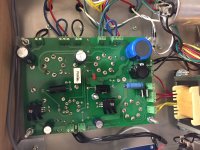
Power section. White (middle of IEC) goes to the chassis ground (as do speaker and input grounds). Bottom of ICE in the picture (hot) goes to 2-Amp slow burn fuse, then to switch on the left. Red shrink tubed black wire is from the PT and then it returns back to the IEC (also has red shrink tube). I didn't have any red wire so I used what I had. I'm leaving out the motor cap and indicator light for now.
Input and Speaker connections. Soldering the ground to the RCA jacks was the hardest part of the build for me.
Screen tap stays disconnected if I'm not running UL mode?
Volume knob. Also challenging to solder for a newbie amp builder like myself. Feel like a bit of a hack, but I've never done point to point soldering before.
Also, there seems to be a SSE start up/test check somewhere, but I can't find it. If someone could someone point me in the right direction I'd really appreciate it.
thanks again...
I've discovered that Chassis work is not my favorite, and the Harbor Freight punches I bought aren't the best tools in my tool box. I had better luck with a step bit.
I haven't plugged it in yet. Please let me know if you see something that's not right...
An externally hosted image should be here but it was not working when we last tested it.
Mock up.
An externally hosted image should be here but it was not working when we last tested it.
I left the PT & OPT leads long until I make sure everything's working correctly.
I'm not sure where to put the 3.5v CT...am I missing something totally obvious?An externally hosted image should be here but it was not working when we last tested it.
Power section. White (middle of IEC) goes to the chassis ground (as do speaker and input grounds). Bottom of ICE in the picture (hot) goes to 2-Amp slow burn fuse, then to switch on the left. Red shrink tubed black wire is from the PT and then it returns back to the IEC (also has red shrink tube). I didn't have any red wire so I used what I had. I'm leaving out the motor cap and indicator light for now.
An externally hosted image should be here but it was not working when we last tested it.
Input and Speaker connections. Soldering the ground to the RCA jacks was the hardest part of the build for me.
Screen tap stays disconnected if I'm not running UL mode?
An externally hosted image should be here but it was not working when we last tested it.
Volume knob. Also challenging to solder for a newbie amp builder like myself. Feel like a bit of a hack, but I've never done point to point soldering before.
Also, there seems to be a SSE start up/test check somewhere, but I can't find it. If someone could someone point me in the right direction I'd really appreciate it.
thanks again...
Hooperstack- Tubelab has several color illustrations of the SSE wiring with different options on how to wire the board.
Wiring Diagrams | Tubelab
Wiring Diagrams | Tubelab
Hooperstack- Tubelab has several color illustrations of the SSE wiring with different options on how to wire the board.
Wiring Diagrams | Tubelab
Thanks, I've been referring to them all along, but unfortunately, the wires are color coded differently than the PT I have, and are not labelled according to the the voltage. I was able to figure out that I had the 3.15v and the 5V backwards by looking thru old posts of other amps.
I also had mistakenly jumped the D1 & D2 positions which are now removed (confusing them for D3 & D4 which is jumped if you don't install a diode). D3 & D4 have D-1N4007 diodes in them, which I believe are installed correctly.
Unfortunately, I still have a short somewhere and I've run out of fuses, so I'm off to the hardware store in hopes of finding a 2 amp slow burn...then more trouble shooting.
Oh, I also noticed that I mis-labeled my wiring in the last post. I have it wired this way: IEC hot>to fuse> PT>IEC neutral. IEC common is ground to chassis along with RCA input and speakers.
Cheers.
I've got sound thru the left channel....thanks to this thread: SSE B+ puzzler
Also, there seems to be a SSE start up/test check somewhere, but I can't find it. If someone could someone point me in the right direction I'd really appreciate it.
When I was building my my SSE, I found this thread to be extremely helpful:
Simple SE checkout for dummies
In post #5, Ty_Bower had a link to his Photobucket account with pictures of the checkout. Unfortunately, this link seems to have been broken / incomplete since I built mine. Still plenty if great info in that thread.
Here's another excellent thread for when you get everything running and want to check bias for your cathode resistors. Post #10 in this thread:
SSE bias questionSSE bias question
Think I need to step back and take a break...
I've found it helpful to take a few days break and come back with fresh eyes.
Btw, not sure if it's just a glitch with my computer, but none of your pictures are coming up in post #3
Thanks Yukon, that's good advice, and I appreciate the links. I actually had the same idea, albeit w/ a shorter time frame. I stepped away from it for the day yesterday and came back later in the evening.
Using a process of elimination I checked the amp from input to speakers. First I checked both inputs for signal: good. Then the volume pot: good. Switched inputs on the board: good. Switched outputs on the board: good. And by good, I mean that I had sound out of one OPT regardless of input/output side of the board, so I knew I had a good signal to/from the board.
Then I swapped the speakers at the jacks which led to the opposite speaker working. Oh no...do I have a bad OPT???
I desoldered both OPT's and checked their ohms on my voltmeter. Both registered 8 Ohms. So they're both good...what the what? why no sound??
Well I figured there's only one thing left: the speaker jack. So I connected the OPT directly to the speaker wire and viola! Both channels working!! great!!
I'm glad to have figured it out and am impressed by the sound coming thru these very old Bose speakers my wife's had since college. I'll figure out the issue with the jack, tidy up the wiring and button up the amp with plans to connect it to the main system and enjoy some music this afternoon.
Idk why those pics aren't working..I'll try and figure that out as well as post some updates.
Cheers!
Woohoo! Music!...
Btw, not sure if it's just a glitch with my computer, but none of your pictures are coming up in post #3
I can view pics in post 3 if I right click and select "open link in new tab." This creates a new tab (Firefox) with Imgur showing the picture. Possible that Imgur does not allow the OP to hot link into DIYAudio.
To Jeff the OP, the motor run caps should have a plastic dielectric, and not be polar. If you can find the caps online, they should specify something like polyester (mylar) or polypropylene. Also, are you still having trouble soldering? I'd suggest a good quality 60-40 or 63-37 tin/lead solder like Kester https://www.amazon.com/Kester-24-6337-0010-Rosin-Solder-SPOOL/dp/B00068IJWC/ref=sr_1_3 and a good temperature controlled station. Get some junk components and old wire and practice.
Last edited:
- Status
- This old topic is closed. If you want to reopen this topic, contact a moderator using the "Report Post" button.
- Home
- More Vendors...
- Tubelab
- Newb has SSE wiring questions