I have completed my first build of an SSE and fired it up on my makeshift bench. When I powered it up the tubes glow a bit but I do not seem to get any sound or hum. I have a Carver pre-amp that I use as an input source, it powers my Carver amp nicely so I know I am getting a signal there.
I used the "basic Triode connected amp without feedback." wiring scheme, I also have a choke and a supplemental capacitor.
Here are some other details that may be of use to help me figure out what is going on:
Here are the key parts I am using:
Input transformer: 274BX - I am using the white and grey wires
Output transformers: 125ESE - The brown and blue are wired to the board, the black and yellow go to the speaker outputs.
Tubes: 6L6GC - JJ Electronics - matched set
5AR4/GZ34 - JJ Electronics
12AT7/ECC81 - JJ Electronics
I did not install the D1, D2 diodes, I have installed the tube as a rectifier, but I did not install a switch, so that circuit is currently open? Should I jumper that to close it? Could this be the problem?
I have grounded everything as per the wiring diagram, I am not using a volume control. I have the multi-meter in the attached picture, is this acceptable for testing and troubleshooting?
Any help would be appreciated.
Scott
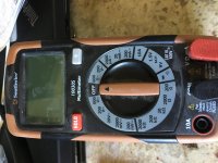


I did not install the D1, D2 diodes, I have installed the tube as a rectifier, but I did not install a switch, so that circuit is currently open? Should I jumper that to close it? Could this be the problem?
No. It should be open, but it actually doesn't make any difference if the diodes are not installed.
You need to start measuring voltages to give us some idea what is going on.
Win W5JAG
Last edited:
Hi, that meter will work. First make sure you read the safety warnings-precautions (on tubelabs website) and have the schematic from tubelab's website. Remove your preamp. Take out your all your tubes. Measure your tubes heater voltage to make sure they all have approximately 6.3 volts ac and 5 volts for rectifier. Check high voltages at rectifier socket. if rectifier heater and high voltages are good, put in rectifier only. Turn on and measure after warmup the voltage across R2 150k ohm resistor. If you have voltage at r2 then check all other tube sockets plate pins for voltage. This is to check for good solder joints and power supplies working. Post resulting voltages. Post more pictures of both sides of circuit board helps to troubleshoot and to see wiring setup. Also if power supply is working with all tubes in, connect a piece of bare wire to either the left input or right input you should hear hum from that side.
Last edited:
Take voltage measurements as per Ty Bower's SSE checkout and report back:
<a href="http://s69.photobucket.com/user/Ty_Bower/media/Simple%20SE/Checkout/ohm00.jpg.html" target="_blank"><img src="http://i69.photobucket.com/albums/i43/Ty_Bower/Simple%20SE/Checkout/ohm00.jpg" border="0" alt=" photo ohm00.jpg"/></a>
Regards,
Charlie
<a href="http://s69.photobucket.com/user/Ty_Bower/media/Simple%20SE/Checkout/ohm00.jpg.html" target="_blank"><img src="http://i69.photobucket.com/albums/i43/Ty_Bower/Simple%20SE/Checkout/ohm00.jpg" border="0" alt=" photo ohm00.jpg"/></a>
Regards,
Charlie
cbutterworth perfect I was looking for something like that to refer scottewine to.
Search threads for : Default SSE checkout: so far so good, but have a B+ question
Post #8 for link to : Default Simple SE checkout for dummies
The complete post is great!
photobucket link in post #5
Search threads for : Default SSE checkout: so far so good, but have a B+ question
Post #8 for link to : Default Simple SE checkout for dummies
The complete post is great!
photobucket link in post #5
Last edited:
I have gone through the list of 20 measurements from the Ty Bower SSE checkout and the results are below. Everything was looking good until I got to the 5 VAC filament voltage, which was 0, as were the high voltages on the rectifier pins.
Poking around I noticed that I get ~420 VAC from the red wires from the transformer, both the yellow wires return 0 volts and one of the green wires give 6.6 volts and the other gives 0, so it seems like there is a problem with the power transformer?
A couple other notes:
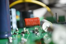
1. The only part that I did not get that was exactly in the list of parts was the C3 capacitor, I think the one I got was basically the same thing, but was wider than the board, so I had to bend the pins to get it to fit, see the attached picture.
2. I made a major noob mistake and put the octal socket for V2 rotated one notch and had to remove it and re-solder it, I don't think I damaged anything but cannot be certain.
3. When installing U10 or U20 (not sure which right now) I got solder connecting two of the pins and had to remove it, which may have heated up the component more it would normally get. The heat sink was on at the time, and I don't think it got that hot, but I cannot be sure.
Here were the measurements that match with the pictures on the checkout:
Resistance:
1. Very high resistance, basically an open circuit.
2. 220k
3. 221k
4. 220
5. 220
6. 221k
7. 221k
8. 549
9. 549
10. 548
11. 548
12. 97
13. 98
Voltages
1. 6.6
2. 6.6
3. 6.6
4. 6.6
5. 0.0
6. 0.0
7. 0.0
Thanks in advance for any feedback you have and let me know if I can get you any more information.
Scott
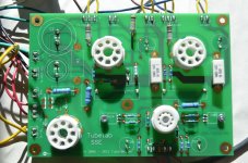
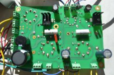


You are in the same boat I was.
D3 D4 and tr1 are your problems,I think. Search tubelab forum for tr1 and you will find the answer, but you could also just jumper all 3
D3 D4 and tr1 are your problems,I think. Search tubelab forum for tr1 and you will find the answer, but you could also just jumper all 3
Ok, I think I found your post. I do not have anything in D3, D4 or TR1, are you saying I need to put in jumpers for each one?
Excellent, thanks! I jumpered all three and now I get all of the correct voltages as per the checkout, in a bit I will put the tubes in and give it a try!
Excellent, thanks! I jumpered all three and now I get all of the correct voltages as per the checkout, in a bit I will put the tubes in and give it a try!
good luck. let us know how it goes.
i really think the build instructions should be amended to include this information. it can sometimes be frustrating if you are given the very nice build guide that is off a little. once you get 3/4 of the way through it, you are trusting it entirely to guide you because of how complete it is..
by the way where did you see the checkout for the sse? i searched and searched and gave up and just popped my tubes in.
Put the tubes in and fired it up and it works great! Thanks for the help, I will have a few more questions as I upgrade a few things and build an enclosure for it.
George! Your assembly instructions are awesome except you need to add that last little bit about the jumpers for D3, D4 and TR1 for the new boards! I have ordered them and will add them in when they arrrive.
Scot
George! Your assembly instructions are awesome except you need to add that last little bit about the jumpers for D3, D4 and TR1 for the new boards! I have ordered them and will add them in when they arrrive.
Scot
Glad you got it working. My board was the older version and with the forum input, I got my SSE working fine a couple of years ago. I have never wired it for ultralinear or cathode feedback because I love the sounds as it is.
Congratulations, I bet you feel very relieved and pleased.
Charlie
Congratulations, I bet you feel very relieved and pleased.
Charlie
its worth trying out some of the options available on the board;
i just set mine up for ultralinear and i found that i might want to use that when listening to rock. mine is still breaking in tho and i am running it as many hours as i can to help speed that along
i just set mine up for ultralinear and i found that i might want to use that when listening to rock. mine is still breaking in tho and i am running it as many hours as i can to help speed that along
its worth trying out some of the options available on the board;
i just set mine up for ultralinear and i found that i might want to use that when listening to rock. mine is still breaking in tho and i am running it as many hours as i can to help speed that along
Well said. It is worth a try. For me, I use the solid state AKSA 55n with Vandersteens for rock and heavy orchestral music, plus some poorly produced CD's.
The Simple SE with Pensil 10.2 single drivers are best with acoustic and non-complex music.
Charlie
- Status
- Not open for further replies.
- Home
- More Vendors...
- Tubelab
- First Tubelab SSE Build - no sound -need troubleshooting help