Not much that can affect both channels identically.
My WAG is that it's working right, and you are seeing a measurement error, perhaps because you do not have the ground lead at an actual ground potential relative to the plate.
Alternatively, are you by any chance using a probe with a divide by 10 setting?
Win W5JAG
My WAG is that it's working right, and you are seeing a measurement error, perhaps because you do not have the ground lead at an actual ground potential relative to the plate.
Alternatively, are you by any chance using a probe with a divide by 10 setting?
Win W5JAG
Starting to think nobody looks at this section of the forums, including George.
I try to check in to this forum every day or two, but the way life has been going there are times that I don't get here that often.
.I see a trace on top side of board connecting the drain of the 10M45's on both channels to B+, there is also a trace on the bottom of the board connecting the drains of the MOSFETs for both channels connecting to B+
I was looking at a board when I first saw this, and came to the conclusion that you had swapped the mosfets and the 10M45's, but before I could post anything I got one of the nearly daily panic calls from my daughter telling me how I had to solve her latest problem. I forgot about this in the two day mess that ensued. I now believe that we have different opinions as to which side of the board is the top. I use the convention that calls the silkscreen (white lettering) side the top. Either way I see the you have fixed it.
I'm a newbie and I'm curious as to why it seems if everyone follows the instructions the amp should work the same for everyone right?
The TSE was not intended to be a DIY amplifier design at the beginning. The first one was for my own use, but my co-workers wanted copies. After a while I couldn't make them fast enough, and I worked in an environment surrounded by thousands of technical people, so I made a CD with some crude instructions and ordered a stack of boards. Many people could make their own, and we even had a couple of group builds.
During one of those "build labs" a co-worker came up with the "let's make a website" idea, and Tubelab was born. In the 10 years since we have all been laid off, and scattered across the country, so Tubelab is just me now. It was stated from the beginning that the TSE is not a simple "build it, plug it in, and play" design. There are also two or three tube choices that require different components, and there have been several variations. In the dozen years since it was designed, there have been several component changes due to component obsolescence.
I had planned to do the instruction manual over, but it is becoming evident that if Tubelab is to continue as a company the TSE design and its manual needs to be redone, as does the entire website.
I am also having trouble getting my Tubelab SE board going.
There are several possibilities here, but the obvious one is the 10M45's. Where did you get them? There have been posts here regarding fake 10M45's sold on Ebay.
Next, we need to see if 10 mA of current is actually flowing through the tube. Make sure that the cathode bypass caps (C8, C10) are installed in the right direction. The positive end should be closest to the 5842 tube. Turn the adjustment pot fully clockwise and measure the voltage at the cathode pin of the 5842 (the ungrounded end of R10 and R21). It should be about 3 volts. With the amp turned off (been off for a minute or two) this same point should measure about 300 to 350 ohms to ground.
Hi George! Yes I got it up and running and my hats off to you, what a great amplifier!! Thank you for what you do for the community.
I wonder if the person I got the board from got the 10M45's from EBay because they were very whacky. The MOSFETs were bad too. I get all my parts from Mouser or Digikey.
I wonder if the person I got the board from got the 10M45's from EBay because they were very whacky. The MOSFETs were bad too. I get all my parts from Mouser or Digikey.
I remember a thread several months ago about some Ebay sourced 10M45's that were basically shorted, which made the 5842's go into nuclear meltdown. 5842's are no longer cheap tubes.
Not sure what's up with mgitterle's amp yet, but 10M45's from anywhere other than a reputable parts house can be suspect.
Not sure what's up with mgitterle's amp yet, but 10M45's from anywhere other than a reputable parts house can be suspect.
I remember a thread several months ago about some Ebay sourced 10M45's that were basically shorted, which made the 5842's go into nuclear meltdown. 5842's are no longer cheap tubes
No fooling, I had 30mA through one and 20mA through the other with matched 1% resistors. I popped the ones in I got from Mouser and it was perfection.
I had no idea anyone would want to make counterfeits of these devices. How strange.
When the 10M45 first appeared anyone could buy then from Digikey. I got 100 on my second order, so I was covered. Within a year, they disappeared and were out of stock for over a year. Then they reappeared at a higher price, and were "authorized for sale to USA buyers only." They were even given an export control number that said that they couldn't be resold overseas. It seemed that they would disappear from Digikey stock, then show a 26 week lead time, then show up a few weeks later. Mouser never had them until later. This went on for at least two years.
After a year or two they became rather easy to get here, but it took a long time for them to be available in Europe or Australia. There were rumors of their use in secret spy stuff, but who knows it could have been a problem at IXYS. A lot of their early parts blew up randomly and for no reason.
After a year or two they became rather easy to get here, but it took a long time for them to be available in Europe or Australia. There were rumors of their use in secret spy stuff, but who knows it could have been a problem at IXYS. A lot of their early parts blew up randomly and for no reason.
Hey guys,
Thank you all for the sage replies. I am working on getting back to the bench to test these ideas out.
I believe that I have authentic IXYS 10M45s.
I think someone asked if I was able to vary the plate voltage on the 5842s by using the cathode trim pots, and I am able to do so, but again, it varies between about 14-18 volts, rather than the 150-180 I was expecting (as measured from the coupling cap lead closest to the 5842s, to the ground trace at the front of the board (which is wired to the ground pin of the IEC). Note that I am using non-polarized capacitors in this position (0.33uF, 450v, brand and type escapes me now, but not boutique).
Another thing I want to ask before I repeat the checkout process again is this: when I adjust the bias pots for the output tubes, which pin on the 45 sockets is the grid connection, assuming I am looking at the board from the front, with the 5842s closest to me?
Second, when I adjust for "most negative voltage," what ballpark of voltage am I looking for (>100, >200, <100)?
I'm not a total newbie to tube electronics, but this is the deepest water I have gone swimming in so far. Lots of fun, but also a lot of frustrating newbie "gotchas."
Thanks again for all the help. I really appreciate you guys.
Marc
Last edited:
which pin on the 45 sockets is the grid connection, assuming I am looking at the board from the front, with the 5842s closest to me?
Left front, for positve ID, it connects through a 100 ohm resistor to the rest of the circuit.
Second, when I adjust for "most negative voltage," what ballpark of voltage am I looking for (>100, >200, <100)?
I'd like to answer this, but I honestly don't recall. Unloaded, it should probably get close to - 150 VDC, maybe more.
Win W5JAG
I think someone asked if I was able to vary the plate voltage on the 5842s by using the cathode trim pots, and I am able to do so, but again, it varies between about 14-18 volts, rather than the 150-180 I was expecting (as measured from the coupling cap lead closest to the 5842s, to the ground trace at the front of the board (which is wired to the ground pin of the IEC). Note that I am using non-polarized capacitors in this position (0.33uF, 450v, brand and type escapes me now, but not boutique).
With the board powered off measure resistance from pin 6 of the 5842's to ground.
Also measure the resistance from any one of these pins to ground; pin 4,5, 7 or 8.
Do the 5842's glow? Measure DC voltage from pin 3 to 9.
Another thing I want to ask before I repeat the checkout process again is this: when I adjust the bias pots for the output tubes, which pin on the 45 sockets is the grid connection, assuming I am looking at the board from the front, with the 5842s closest to me?
Front left. For 45's you will want probably around -50v to -60v referenced to ground.
Second, when I adjust for "most negative voltage," what ballpark of voltage am I looking for (>100, >200, <100)?
Negative rail is -150v, I can't recall what you can get from that on the grid but it's close. But for 45's I would just start out at -60v on the grid, I think I ended up at -50 for 32mA.
OK.
- I'm getting B+340. B- ~150.
- I can get the grid voltage on the outputs to around -100
- Plate voltage on the 5842s is 9v on the left and 14.5 on the left, measured from the front leads of C9 and C11 and these do not vary when I adjust R9 and R20
- 5842s glow.
- Voltage between pin 3 and pin 9 on 5842s is zero.
- Resistance measurements on 5842 sockets to ground:
Pin 4 - 320 both channels ."
Pin 5 - "1 ." both channels
Pin 7 - R "2.8" on 20K range, L "2.6" on 20K range
Pin 8 - ".L" all ranges
Pin 9 - "1.4" on 200M range
I hope this makes sense to someone.
Thanks for all the help. Very much appreciated.
Marc
KF5IAE
Voltage between pin 3 and pin 9 on 5842s is zero.
Make sure you are reading DC volts, you should have 6 volts there across the two pins.
Resistance measurements on 5842 sockets to ground:
Pin 4 - 320 both channels ."
Pin 5 - "1 ." both channels
Pin 7 - R "2.8" on 20K range, L "2.6" on 20K range
Pin 8 - ".L" all ranges
Pin 9 - "1.4" on 200M range
Well to me something doesn't look correct. Do you have a volume pot installed? If so does turning up the volume pot to max volume increase the 320 ohm reading from pin 4 to ground?
Pin 5 should be open and not 1 ohm, same for 7 and 8.
You forgot to read from pin 6 to ground, that's the cathode. When taking this reading move the bias adjustment pot and see what happens.
Well to me something doesn't look correct.
I agree that something is not adding up here. Pins 4,5,7 and 8 are all connected together inside the 5842 tube, so they should all have the same voltage on them, and the same resistance reading.
Are these real 5842 tubes, and not the Russian "equivalent" being sold on Ebay? Those are not equivalent.....different pinout.
What voltage do you have on the 5842 plate (front of C9 and C11) with NO 5842 tube installed? It should be full B+ voltage.
- 5842s glow.
The heater element inside the cathode of the 5842 should be glowing orange. The outer metal plate should not be glowing.
Voltage between pin 3 and pin 9 on 5842s is zero.
If there is a glow inside the 5842, there has to be voltage between these two pins.
Can you check the voltages on the 10M45? Maybe they are installed incorrectly?
If the two resistors associated with each 10M45 are swapped, it will cause a low plate voltage, low but usually somewhat adjustable......
Pin 5 should be open and not 1 ohm, same for 7 and 8.
Pins 5, 7 and 8 are not connected on the PC board, and will be open (infinite resistance) with no tube installed. They will all be connected to pin 4 with a genuine 5842 or WE 417 installed. The resistance from this pin to ground should be about 120K with no volume control, and vary from zero (volume all the way down) to about 50K (volume up full). Zero or very low all the time.....input connections from jacks to the board are shorted or swapped. This still will not cause wrong voltage on the plate. A positive voltage from a source like a cell phone earphone jack WILL. Make readings with no input connected.
OK. My bad. I measured from the 5842 socket pins, without the tubes in place. I will redo these measurements this morning, with tubes in place.
Thanks again for all the advice.
There is no volume control. I wired an RCA cable to the board temporarily for testing. It was not plugged in to a source when I made those (erroneous) measurements.
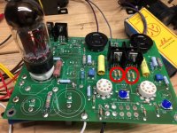
Also, I am posting photos of my board, just in case someone spots something obvious.
Marc
KF5IAE
https://plus.google.com/u/0/photos/...301313685906?icm=false&authkey=CMewztGn876SQQ
https://plus.google.com/u/0/photos/...25037443314?icm=false&authkey=CL6Fh7nr17398wE
Thanks again for all the advice.
There is no volume control. I wired an RCA cable to the board temporarily for testing. It was not plugged in to a source when I made those (erroneous) measurements.
Also, I am posting photos of my board, just in case someone spots something obvious.
Marc
KF5IAE
https://plus.google.com/u/0/photos/...301313685906?icm=false&authkey=CMewztGn876SQQ
https://plus.google.com/u/0/photos/...25037443314?icm=false&authkey=CL6Fh7nr17398wE
Last edited:
It looks like to me you got 330k instead of 332 for the current set resistors R16 and R27.
Good eye.

jeff
You guys were right on. I swapped out the 330Ks for 330s. I guess all those extra zeros really make a difference, ") . It reminded me of Michael Keaton in Mr. Mom: "220, 221, whatever it takes." That is, total rube move. Thanks for spotting it.
. It reminded me of Michael Keaton in Mr. Mom: "220, 221, whatever it takes." That is, total rube move. Thanks for spotting it.
Was able to set both 5842s to 175v. However, I can adjust the current across the left output shunt to more than 70, but I can't get the right to more than 25 or so. If I reduce the left bias, I can get them equal at 25mA. I'm testing it with 2" speakers, but it sounds pretty good for the most part, but once in awhile seems to be clipping.
. It reminded me of Michael Keaton in Mr. Mom: "220, 221, whatever it takes." That is, total rube move. Thanks for spotting it.Was able to set both 5842s to 175v. However, I can adjust the current across the left output shunt to more than 70, but I can't get the right to more than 25 or so. If I reduce the left bias, I can get them equal at 25mA. I'm testing it with 2" speakers, but it sounds pretty good for the most part, but once in awhile seems to be clipping.
Swap the output tubes and see if the current follows the tube (likely). 45's shouldn't need more than about 30 mA.
I have a collection of well used 45's. Some will do 100mA, some barely make 35. All sound good on most music but the ones that can deal with the higher current demands seem to be more dynamic especially on music that's full of transients. Only the strong tubes would work in a 15 watt AB2 push pull amp that I put together several years ago.
I have a collection of well used 45's. Some will do 100mA, some barely make 35. All sound good on most music but the ones that can deal with the higher current demands seem to be more dynamic especially on music that's full of transients. Only the strong tubes would work in a 15 watt AB2 push pull amp that I put together several years ago.
- Status
- This old topic is closed. If you want to reopen this topic, contact a moderator using the "Report Post" button.
- Home
- More Vendors...
- Tubelab
- Tubelab SE bias issues