So after running my TSE for a month with alligator clips and the like I had to put everything away so we could prepare our house for sale.
I sold off the 120V Edcor 131 and bought a 240V one ready for the move.
Being as I am selling off my Magnavox 185 modified amp I figured I should finish the build of the TSE so we continue to have music once the Maggie sells.
So I set up a space in the back of the basement and laid everything out ready for the final build. I'll likely needs lots of help as this progresses and I'll try to take plenty of pictures so it may be helpful to another newbie like me.
I did complicate matters by deciding to have an umbilical connection to the PS but Boywonder, who inspired me to do this, has been super helpful (along with evanc and a few others).
Grounding still confuses me a bit but I'll try to get the hang of it 😱
It'll take a couple of weeks to get this finished but I think the final build is going to look stunning and sound amazing. Fingers crossed!
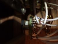
Been working on wiring the umbilical cord. probably should have used different color wires for each transformer wire but I had a huge roll of Orange 600V Teflon coated wire so that will have to do 🙂 It's not as hard as it sounds as I have 8 wires plus a non Orange wire for the signal ground.
Will post pictures of the progress at the weekend.
Will post pictures of the progress at the weekend.
Umbilical complete; pictures to follow.
I am using RG174 cable for the signal (RCA input to selector). It is sinle conductor with a shiled braid around it. I understand how to connect the red and black RCA terminals to the selector but do I have to connect the braid to the input RCA? If so, how?
I plan to run a single wire from all the input RCA's to ground on the PCB; is that the right way to do it?
Thanks.

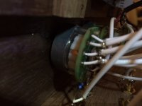
The wrap frayed whilst I was soldering so I had to use some electrical tape to hold it together. Not as tidy as I would like but functional and will be hidden anyway. May redo it at some point.

You can prevent the fraying by melting the ends of the wrap. There's a tool for that, but a soldering iron will work as well. Just clean the tip well after you're done (or use a tip you don't care about). Heat shrink would have looked more professional than electrical tape, but the tape does the job.
Tom
Tom
Actually I have ordered some heatshrink so I may well be able to tidy it up if they have a large enough option in the assortment.
Thanks for the tips.
Thanks for the tips.
I would run a piece of you coax from each input RCA to the selector and then run the coax to the volume controm and then to the board. This way the hot and return stay close together the whole way.
Evan, I think I get what you mean. I won't have chance for a couple of days to lay out a representation of what I think you mean but when I do I'll photograph it and post it and see if it matches.
Thanks for your continued help, mate.
Thanks for your continued help, mate.

So here is my thought (based on my (mis) interpretation of Evans post) on wiring the inputs and selector and attenuator (leaving out the 'out' from the attenuator). The coax is single solid wire with a shield so if I follow this approach and ground the signal of the 6 inputs to the board via the attenuator, do I need to keep the shield from touching anything on the rca's/selector/atten or have it touching the RCA's?
Am i correct in grounding the rca's to a safety ground? They are metal of course and are in a wooden chassis.
I take it the selector and attenuator also need to follow that path to safety ground too?
Thanks.
I'll take a picture for you when I get home.
Isolate the rca inputs from the chassis.
Run the hot and ground from each rca input to the selector using coax.. Here I combined all the left input grounds and right input grounds.
From the selector to the attenuator I ran two pieces of coax carrying the hot and ground for each channel.
At the attenuator the left and right ground come together.
From the attenuator to the board I used microphone cable ...two conductors with a ground. This carries the left and right hot as well as the single input ground to the board. You could keep the grounds separate all the way to the board and use two pieces of coax instead of the single balanced cable from attenuator to board.
So I don't get where the ground connects to the selector?

Also, the chassis is walnut so the RCA's are isolated from any metal already. Don't they need to safety ground anyway? This stuff is mind-numbing 🙂
Also, the chassis is walnut so the RCA's are isolated from any metal already. Don't they need to safety ground anyway? This stuff is mind-numbing 🙂
on the TSE board there is a ground connection right next to c5 labeled gnd2. I used this to hook the board to safety ground. There is no ground loop braker on my amp and it is quiet.
On my Aikido preamp, I ran signals from the RCA to the selector, then from the selector to the attenuator.
For the signal ground, I ran a ground buss across all the RCA grounds to either the pcb ground or to ground point near the IEC.
I don't know if this info helps at all.
Charlie
For the signal ground, I ran a ground buss across all the RCA grounds to either the pcb ground or to ground point near the IEC.
I don't know if this info helps at all.
Charlie
- Status
- Not open for further replies.
- Home
- More Vendors...
- Tubelab
- So the final build begins