Hi Mooly,
Now it sounds worrying. From the sounding, I dont think I can hear any problems. The application is buffers used in Lite Audio DAC-AM.
Do you suspect any problem or how can I check without a scope? I only have a DMM.
You really need a 'scope to check what's going on. If it's hot there is a problem. You could try adding a 0.1uf cap (or thereabouts) directly across the supply pins (4 and 8) and see if that helps.
You really need a 'scope to check what's going on. If it's hot there is a problem. You could try adding a 0.1uf cap (or thereabouts) directly across the supply pins (4 and 8) and see if that helps.
Is it across the pins or from pin 4 and 8 to ground?
What type of cap? Electrolyte will work or something more sofisticated?
Across the pins, not to ground.
You want a cap with low impedance at HF so while a good electroylitic may well be OK a small ceramic or polystyrene is much better.
Thanks - what happen if it's to ground? Is it just decoupling?
Thanks - what happen if it's to ground? Is it just decoupling?
If it's to ground any noise on the rails is coupled and injected into that ground system. If that ground is shared with the audio then you have just degraded the noise/distortion performance of the amp.
It's a small point, but an important one.
Across the pins, not to ground.
You want a cap with low impedance at HF so while a good electroylitic may well be OK a small ceramic or polystyrene is much better.
Noted. Thanks.
If it's to ground any noise on the rails is coupled and injected into that ground system. If that ground is shared with the audio then you have just degraded the noise/distortion performance of the amp.
It's a small point, but an important one.
I dont understand this point. Most application I knew, has PS decoupling caps.
I dont understand this point. Most application I knew, has PS decoupling caps.
PSU rails have noise on them... spikes, transients etc... might be small but they are there in some form or another.
Caps pass AC... so if you couple that rail into a ground, and that ground is shared or used as an "audio" or "signal" ground as well as just being a PSU ground then you have just coupled noise into it.
Does it matter ? Yes, because even a few millimeters of print has significant resistance/inductance etc and that "noise" will develop a volt drop across that print which then finds it's way into the audio path. It's a very real effect. Look at all the threads on DIY about amps that hum and buzz. They are extreme examples, but it's because the subject isn't fully understood and appreciated.
Ok, Then how will we resolve this problem as most application requires us to put a decoupling capacitor from supply pin to ground to improve transient. Put the PS, for example regulator, right at the supply pin? But for this method, most of the time is not feasible isnt it?
Ok, Then how will we resolve this problem as most application requires us to put a decoupling capacitor from supply pin to ground to improve transient.
By using separate PSU and signal grounds and a proper grounding plan.
To get the best performance you have to make it feasable.But for this method, most of the time is not feasible isnt it?
however,
in practice opamps aren't going to deliver much in the way of current anyway... so the PSU load is essentially constant. You don't need large caps to supply "transient" currents to the load as there aren't any.
The most important thing is to have solid decoupling across the supply pins of the opamp, which is where it matters and to make sure that if the supply is noisey that it can not get into the grounds.
I’ve been following this topic with great interest!!
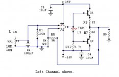
Can anyone recommend a dual FET opamp to replace the OPA2134 in the attached circuit (15v rails)?
Note that R7 and R9 are resistors with value 10 ohms – the headphone amp runs in class A up to 100mW.
Cheers!
Can anyone recommend a dual FET opamp to replace the OPA2134 in the attached circuit (15v rails)?
Note that R7 and R9 are resistors with value 10 ohms – the headphone amp runs in class A up to 100mW.
Cheers!
Attachments
Last edited:
Dude stop repeating this nonsesnse!If it's to ground any noise on the rails is coupled and injected into that ground system.
Plese show me how the HF noise produced in an OpAmp supply rails is INJECTED into the ground by decoupling the supply leads to the ground!
Show the internal class AB transistors, the OpAmp load (resistor to the ground, usually in the feedback loop) and what is the path of the current.
I don't think so. It is a classic class AB in my opinion.Note that R7 and R9 are resistors with value 10 ohms – the headphone amp runs in class A up to 100mW.
The OpAmp that you hav ethee I think is pretty good for that job.
Last edited:
Dude stop repeating this nonsesnse!
Plese show me how the HF noise produced in an OpAmp supply rails is INJECTED into the ground by decoupling the supply leads to the ground!
Show the internal class AB transistors, the OpAmp load (resistor to the ground, usually in the feedback loop) and what is the path of the current.
You don't understand the theory...
You have to pick some point as ground whether it be for a signal reference or for measurement purposes etc, and that ground has some small resistive element to it. Imagine a piece of print maybe a few cm long on a PCB... a piece of ground print. If you take one end of that print as a "reference" and have a cap from a rail returned to the other end of that ground, then any disturbance on the rail causes a current to flow in the cap. That current is returned via that ground print to the PSU ground and in so doing develops a volt drop along that ground corresponding to the "noise" on the rail.
Where the audio problem arises is that there may well be feedback returns and signal grounds "along" this few cm of print and so this "noise" is developed between nodes and finds it's way into the signal path.
Sonic_real _one,
Form your other posting in another thread,
" Low ESR caps are not good on the power lines, regardless of the location (before or after regs). Inductance of the power strips coupled with capacitance under variable load creates oscillations that need to be damped. Usually, the "normal" ESR values are enough to do that damping, but if you go on the low ESR route, there will be some ringing or worse.
Low ESR caps are to be used only series with the signal or where are employed means to damp the oscillations. Or oscillations don't matter - switched PS."
So here you are saying that there can be disturbance on the rails.
So I ask you") if you then couple that into a ground that is used for signal reference points/feedback etc, what is the result ?
if you then couple that into a ground that is used for signal reference points/feedback etc, what is the result ?
Form your other posting in another thread,
" Low ESR caps are not good on the power lines, regardless of the location (before or after regs). Inductance of the power strips coupled with capacitance under variable load creates oscillations that need to be damped. Usually, the "normal" ESR values are enough to do that damping, but if you go on the low ESR route, there will be some ringing or worse.
Low ESR caps are to be used only series with the signal or where are employed means to damp the oscillations. Or oscillations don't matter - switched PS."
So here you are saying that there can be disturbance on the rails.
So I ask you
if you then couple that into a ground that is used for signal reference points/feedback etc, what is the result ? 
- Home
- Member Areas
- The Lounge
- The Best Sounding DUAL opamps