PMA I agree with you that Xtalk is important. It is a bit of embarrassment that the A21 did so relatively poorly on this test. It's physical design was out of my hands, and done independently in Taiwan and not until recently did I actually get to see or test one.
My associate, Carl Thompsen, was NOT asked by Parasound to do the layout of this particular design, and I only OK'd the 'simplified' schematic. This amp was not designed to compete with the JC-1, and in certain ways it shows.
It has done very well in the audio marketplace, however, but I gave away my A21 to my associate for his video theater system. It was designed to be there, not in the 'hi end'.
To my shock at RMAF, a few months ago, I found that Dave Wilson was driving 2 THOR ultra sub woofers with an A21. Of course he did not use it for the main drive, but I was surprised how well it worked for that application.
The biggest weakness of the A21, in my opinion, is its relative inability to drive low Z loads without significant (measurable) higher order distortion. Below 4 ohms, it failed my personal criteria, but then the speakers that it has to drive drop as low as 2 ohms with the latest speakers, and to less than 1 ohm for the previous speakers in my living room, but that is my challenge, hopefully not yours.
I think that an amp the size and power of an A21 is optimum for a number of applications, and I do understand the potential of the improvements you made with it.
I would LOVE to make a really high quality amp with the same power, with Carl's layout, more output devices, and other 'improvements' but I have not been asked to do so. It would double the price, but so what?
Last edited:
EDIT2 - jn this was 1998")
I find myself in the exact same situation as John Curl. Many of the books I am reading are old ones. E/M stuff from the 40's and 50's, clock stuff from 1905 through '57, lathe books from '42..so much learned, so much to go.
This high end audio stuff is just so fascinating. Neglecting some of the most basic principles..
jn
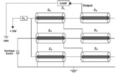
sigh" the artist might have missed a couple of ground staring issues.
Yah. I wasn't going there. I'm not sure that was the point of the drawing anyway.
Last edited:
It was driven simply with soundcard (Lynx L22) in loopback (desktop computer), one channel driven to 10W, second ( measured channel) input terminated with 50ohm and both channels input pins 1 connected together. CD or "ordinary" preamp cannot reach so low crosstalk levels. I had interest to know this about power amp.Nice data.Did you drive it with a stereo preamplifier or CD, or did you use only one input as PMA did?
Bonzai, Oh you mean THAT distortion (second harmonic) that dominates many of my amp designs, even though they are fully complementary. It has to do with the relative asymmetry between N and P mosfets. That will go soon, but it doesn't make much difference in my opinion. I forgot that there were people who actually judge measurements as everything. I personally have found that a little second harmonic (.01%) doesn't do much harm.
Someone mentioned here that inductance of coaxial cable shield is zero. Such statement is a nonsense, please check very basic equations (hollow cylinder)
Inductance, Self Induction, Inductance Of A Solenoid - Transtutors
Inductance, Self Induction, Inductance Of A Solenoid - Transtutors
did you use only one input as PMA did?
The second input was used as well, with cable terminated by resistor and cable shields connected at generator.
JN, in case you want to know power amp channel separation, you cannot use neither CD nor preamp. Preamp could be used only in case it was a dual-mono with 2 separated PCB board and two power supplies. The preamp with one common PCB and power supply will never get -117dB/10kHz. Neither will any CD player. This would be difficult to achieve even with rotary stepped attenuator as a single component! Do you ever measure audio components?

 May the xtalk gods be with you and all ......
Someone mentioned here that inductance of coaxial cable shield is zero. Such statement is a nonsense, please check very basic equations (hollow cylinder)
It is very important that you read sentences very carefully.
Here is my statement again.
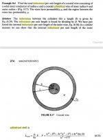
Note the word "internal", I hilited it for you. Also note the discussion of the finite thickness and how there will be magnetic flux within the actual finite shell of the braid.The internal inductance of a cylindrical wire is 15 nH per foot. This is INDEPENDENT of the diameter of the conductor.
The internal inductance of a cylindrical braid is very close to zero. To wit, it will be close to the braid strand diameter divided by the circumference of the braid. For reasonable braids, that might as well be zero.
There is no internal magnetic field within a shell of a hollow cylinder. This is a consequence of Amperes law. Derive it yourself if you wish. Don't bother searching the web for something you think may disagree with me, because that will require you understanding it a bit more. Horrors....knowledge..
So now you are reduced to trying to nitpick the statement "very close to zero" and "might as well be zero" to "is zero"? Act like an adult.
And who cares? The point is, you are measuring something which is of no use to the end customer, that being some ridiculous arbitrary test method which is not what the customer will use it for.JN, in case you want to know power amp channel separation, you cannot use neither CD nor preamp. Preamp could be used only in case it was a dual-mono with 2 separated PCB board and two power supplies. The preamp with one common PCB and power supply will never get -117dB/10kHz. Neither will any CD player.
Worry about what I told you. How your amp design may compromise the entire system.
Yes. I am also responsible for measurements by others using equipment which I wire into place. Equipment which is orders of magnitude more demanding than anything you will ever design. And, it is done in an environment where there are the ground loops from H#LL present.Do you ever measure audio components?
jn
ps. One of my co-workers derived it himself..it was essentially a freakin notebook. I understood the derivation entirely, for at least half a page.
after that, I took his word.My avatar is actually a braid in braid, note the black region in the center...that is because a cylindrical braid has no magnetic field inside the inner wall of the shell.
Last edited:
Happy New Year to all!
And to you as well.
This discussion has been quite stimulating, I thank you for that.
jn
and from a small market town in the Scottish Borders, a Happy New Year to all, and Peace in the World - and in this thread!
Not as beautiful as Prague, but with a simple rustic charm - such as the empty whisky bottle in the foreground!
(Kelso was a centre for free Polish people in the 1940s...in the town hall there is a large plaque expressing their gratitude. Many stayed here and are now well established as 'new' Scots.
Attachments

Last edited:
Man, can't believe what I had to do to get this into a jpeg..sigh.Someone mentioned here that inductance of coaxial cable shield is zero. Such statement is a nonsense, please check very basic equations (hollow cylinder)
Note that the equation includes the thickness of the shell. What you linked to doesn't consider the shell thickness, so I don't know what assumptions were made to simplify that equation.
Nonetheless, your linked equation is not accurate. Note that this one includes the permeability of the shell material as well, muC.
Me personally, I'd use the 15nH times (shell thickness/shell circumference), which I've said from the get-go, was an approximation.
jn
Attachments
Last edited:
Yah. I wasn't going there. I'm not sure that was the point of the drawing anyway.
Thanks, they pull out old datasheets and put badness back in and now we have no review. I don't have the energy to fix all tihis old stuff.
Bonsai, it is not important to get below 0.01%, as it is inaudible. The designer probably knows what he is doing. Avoiding unnecessary circuit complexity, danger of invisible local oscillations, EMI susceptibility. Fight for ppm's is useless. It counts only on paper or in simulation competition.
PMA, yes I agree. Happy New Year and begs wishes for 2014.
and from a small market town in the Scottish Borders, a Happy New Year to all, and Peace in the World - and in this thread!
Not as beautiful as Prague, but with a simple rustic charm - such as the empty whisky bottle in the foreground!
(Kelso was a centre for free Polish people in the 1940s...in the town hall there is a large plaque expressing their gratitude. Many stayed here and are now well established as 'new' Scots.
LOL.
Hope it was a Taskelder or similar :0
Bonzai, Oh you mean THAT distortion (second harmonic) that dominates many of my amp designs, even though they are fully complementary. It has to do with the relative asymmetry between N and P mosfets. That will go soon, but it doesn't make much difference in my opinion. I forgot that there were people who actually judge measurements as everything. I personally have found that a little second harmonic (.01%) doesn't do much harm.
I agree John. I've just finished a preamp design that is pure second until close to the onset of clipping. JFET input stage BTW.
Happy new year and best wishes for 2014.
Thanks, they pull out old datasheets and put badness back in and now we have no review. I don't have the energy to fix all tihis old stuff.
You know, at first I thought the diagram was some kind of cascaded blumlein voltage multiplier since the coax cables shield wasn't connected.
jn
Attachments
Trolling, heh?
Why would I troll. No need to.
My point is what reviewers look for / want is not necessarily in any way connected to good audio engineering.
Example: review of Zanden CD player that got a substantially positive endorsement in the subjective listening test and was subsequently sleighed in the technical review.
- Status
- Not open for further replies.
- Home
- Member Areas
- The Lounge
- John Curl's Blowtorch preamplifier part II