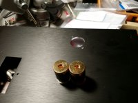
Is there a reason the speaker terminal cutouts have to be so freaking close? I can barely fit a sheet of paper between the connectors, and if I unscrew one so it's even slight loose it'll bump into the other one and short! 
How hard could it have been to space them a couple of finger widths apart?
Since I'll have to drill at least one new hole on each side, what's a good way to cover the unused ones?
(This is the "Deluxe" 4U case.)
How hard could it have been to space them a couple of finger widths apart?
Since I'll have to drill at least one new hole on each side, what's a good way to cover the unused ones?
(This is the "Deluxe" 4U case.)
Attachments
Well, I tried drilling out extra holes, but it's not really viable and they clearly need to be milled. I don't have a mill and have no inclination to find or buy one... So chucking this case and will look for someone who will sell me one with custom holes - a lot of ebay vendors seem to suggest they will do that. Keeping the nice heat sinks though as they may come in handy some day.
Well, I tried drilling out extra holes, but it's not really viable and they clearly need to be milled. I don't have a mill and have no inclination to find or buy one... So chucking this case and will look for someone who will sell me one with custom holes - a lot of ebay vendors seem to suggest they will do that. Keeping the nice heat sinks though as they may come in handy some day.
If it's a removable panel you can get a custom panel made at Front Panel and probably others. No need to chuck the case.
Thanks - yeah, after some consideration I decided keeping it is the way to go.
And since the keep the chassis I decided to try make those damn holes. The problem was I couldn't step up to the 1/2" bit because the next smaller size I have was too much of a step, and the 1/2 would just bit into the edge. So I use the smaller bit as a sacrificial mill bit... and with a bit of heavy-handedness got it big enough for the 1/2" bit and some serious clamping action to keep it put. Of course, I have a really poor press drill which doesn't help...
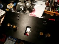
But I got it done, and it didn't end up half bad! Deburred the holes and mounted the posts. A little bit of placement error, but at least it's symmetric. Only a few minor scrapes that can probably be blackened out.
Here it is with the Neutrik XLR connectors in place. Waiting for an IEC 320 block to go in the middle, and a bag of 1/2" plastic hole caps - apparently the latter is a popular automotive part. I had no idea!
And since the keep the chassis I decided to try make those damn holes. The problem was I couldn't step up to the 1/2" bit because the next smaller size I have was too much of a step, and the 1/2 would just bit into the edge. So I use the smaller bit as a sacrificial mill bit... and with a bit of heavy-handedness got it big enough for the 1/2" bit and some serious clamping action to keep it put. Of course, I have a really poor press drill which doesn't help...
But I got it done, and it didn't end up half bad! Deburred the holes and mounted the posts. A little bit of placement error, but at least it's symmetric. Only a few minor scrapes that can probably be blackened out.
Here it is with the Neutrik XLR connectors in place. Waiting for an IEC 320 block to go in the middle, and a bag of 1/2" plastic hole caps - apparently the latter is a popular automotive part. I had no idea!
Attachments
- Status
- This old topic is closed. If you want to reopen this topic, contact a moderator using the "Report Post" button.
- Home
- The diyAudio Store
- diyaudio amp case rear panel speaker connector cutouts