Hello everyone,
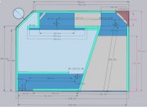
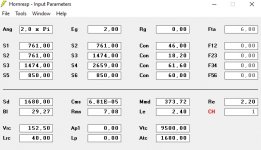
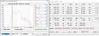
Is this simulation correct ?
The simulation has used a B&C 21DS115 - 4 Ohms speaker.
Do you thing that S1 is too high for the compression ?
Size ; 104 x 75 x 65
Thanks for your help.
Regards
Axel
Is this simulation correct ?
The simulation has used a B&C 21DS115 - 4 Ohms speaker.
Do you thing that S1 is too high for the compression ?
Size ; 104 x 75 x 65
Thanks for your help.
Regards
Axel
Attachments
Last edited:
Some pointers and a suggestion
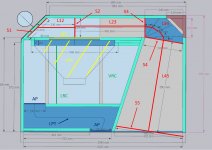
1. Use the "Par" option not the "Con" option to sim all horns folded up into a box in such a manner that two sides of the horn are parallel to each other.
2. That layout is really a CH1 layout, as the driver is offset in the horn path, not directly at the closed end of it. It can also be sim'd as an OD horn with a rear vented chamber - the method I'd suggest as it gives you an extra segment to work with.
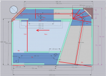
3. Consider the layout I've suggested below, which involves changing the horn path a bit and moving the driver up a bit. I've also changed the entrance and exit of the rear vent. In fact, if you move the driver like I've suggested, you can place the vent parallel to the horn which removes at least one bend from it.
4. Horn CSA sections should be calculated orthogonal to the path, and the path should be down the center of the horn.
5. The path length calculation around the bend might be off a bit. I put in some rough lines which might give a better path length.
6. Calculate Vtc from the the volume of the driver cutout AND the volume of air contained by the driver's cone. Then set Atc to the CSA of the cutout and calculate Ltc from Vtc/Atc.
7. The big chamber is definitely going to need bracing
8. Consider how you are going to insert and remove the driver in this box.
1. Use the "Par" option not the "Con" option to sim all horns folded up into a box in such a manner that two sides of the horn are parallel to each other.
2. That layout is really a CH1 layout, as the driver is offset in the horn path, not directly at the closed end of it. It can also be sim'd as an OD horn with a rear vented chamber - the method I'd suggest as it gives you an extra segment to work with.
3. Consider the layout I've suggested below, which involves changing the horn path a bit and moving the driver up a bit. I've also changed the entrance and exit of the rear vent. In fact, if you move the driver like I've suggested, you can place the vent parallel to the horn which removes at least one bend from it.
4. Horn CSA sections should be calculated orthogonal to the path, and the path should be down the center of the horn.
5. The path length calculation around the bend might be off a bit. I put in some rough lines which might give a better path length.
6. Calculate Vtc from the the volume of the driver cutout AND the volume of air contained by the driver's cone. Then set Atc to the CSA of the cutout and calculate Ltc from Vtc/Atc.
7. The big chamber is definitely going to need bracing
8. Consider how you are going to insert and remove the driver in this box.
Attachments
Hi all,
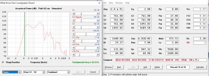
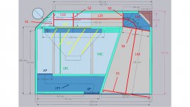
I have done the suggested changes.
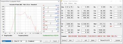
In attch you can find the box, the offset driver simulation and the compound simulation (before the suggested modification)
Maybe I have made an error but the simulation is curious compared to the previous one (compound vs OD).
What do you think ?
Regards,
Axel
I have done the suggested changes.
In attch you can find the box, the offset driver simulation and the compound simulation (before the suggested modification)
Maybe I have made an error but the simulation is curious compared to the previous one (compound vs OD).
What do you think ?
Regards,
Axel
Attachments
Last edited:
In the OD sim, set S1 to be the same as S2. Remember that the CSA must always be measured orthogonal to the path. Also, use "PAR" not "CON" for all segments. Oh, and the first sim should be "CH1", not "CH"
To ensure that the sims are as close as possible, select the "Schematic" option under Loudspeaker Wizard and check the net volumes of each sim. If done right, they should be close, if not identical.
To ensure that the sims are as close as possible, select the "Schematic" option under Loudspeaker Wizard and check the net volumes of each sim. If done right, they should be close, if not identical.
Derive and use the semi-inductance parameters for that driver. The semi-inductance parameters can be derived using the driver's impedance curve, a tracing program (to generate the corresponding ZMA file) and the semi-inductance workbook available from my site.
The sag in the center of the passband in your sim suggests that Fb might be too high and/or the box is too large for the driver.
The sag in the center of the passband in your sim suggests that Fb might be too high and/or the box is too large for the driver.
Derive and use the semi-inductance parameters for that driver. The semi-inductance parameters can be derived using the driver's impedance curve, a tracing program (to generate the corresponding ZMA file) and the semi-inductance workbook available from my site.
The sag in the center of the passband in your sim suggests that Fb might be too high and/or the box is too large for the driver.
Have you seen any measurements of paraflex cabinets (or anything regarding the B&C 18ds115-4) where the affect of either of the 3 lossey as red LE features or black, or green semi are giving the closest results. Im hammering on one in sims as its breaking in and it is very difficult to choose wherevto go on that LE option alone. Ill under or over damp the heck out of the thing one way or the other. But its buttery smooth in the red LE and its not the first, as a cheap 12 car audio turd fairs well and is incredibly popular. I dunno what is ideal. Theres a lot to consider at amy level in any hard pressure entry and or long paths to another thats no longer out of phase in any asy not sorted in that new PH sim. etcAnd the QES penalty of red LE murders higher Qes TS parameters where the other(semi) seems to be legit and vice versa as i cant find much 18ds115 except for bjorno had a tqwt somewhere when he used to post options for everyone (rip good guy) and the green was used there.
- Home
- Loudspeakers
- Subwoofers
- Is this simulation correct in Hornresp ?