I have accidently stumbled across something kind of interesting, if you simulate a gradient subwoofer setup using a pair of dipoles spaced closer than realistically practical, you get some amazing directivity, with fairly low dB rear lobes
You can't put a H or U frame close enough, and I suspect a flat panel dipole would cause reflections to the next flat panel dipole and not work like expected.
You might ask, if it is closer spacing than realistically practical, what is the point?
I think I might have sorted out how to place the dipoles close enough together.
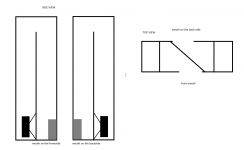
A bandpass allows us to have the sound source from a point different than the speaker cone, so if you made a dipole from a pair of bandpass subwoofers with slot ports adjacent, and another dipole pair immediately adjacent to it you could space it extremely close together
Four bandpass subwoofers built in one box, four channels of DSP needed to get the delays, and four channels of amplifiers. You could not get anywhere near the directivity with just an end fire or line array with that few of drivers, certainly not in such a small package.
Sure it is not exactly efficient or simple, and the box design and planning may rival horn folding complexity to get the box design sorted out, but it sure does seem promising.
What am I overlooking or mistaking?
This is that thread that is sending myself down some odd rabbit holes by the way:
https://www.diyaudio.com/forums/software-tools/370366-software-design-multi-driver-directional-setup-kii3-beolab-90-a.html
32 Hz to 125 HZ, probably slightly wider than an ideal bandpass but close enough.
Total distance between sources of 20" that is easily enough space for four slot ports, and 3/4" wall thickness.
Looks like frequency range and distance can go higher without blowing up, i.e., this is not right on a cliff on a design as far as I can tell.
I have only used a subwoofer excel spreadsheet setup for arrays to test this, so would love to know if it holds true in proper modeling.
Last edited:
You went from dipoles to bandpass...
Both, not separate things.
You can make a dipole out of a pair of omnidirectional speakers. I am thinking build a dipole out of a pair of bandpass.
So a gradient subwoofer, but instead of a pair of omni speakers, a pair of dipoles for greater directivity, and each dipole is made from a pair of bandpass to be able to get closer spacing. Total of four bandpass to make a gradient subwoofer
Slot ports spaced one against another. With 3" slot ports and 3/4" walls, the length would be less than 16" Can't come anywhere near that close spacing with an H or U frame dipole.
Kind of like this, ports 1, 2, 3, 4
<=-Length->
[1][2][3][4]
Ports would be slot ports with the small direction lined up along the length.
Obviously the width and depth would be larger than the length and likely take some planning to orient everything.
So am I missing something obvious why this wouldn't work?
- Status
- This old topic is closed. If you want to reopen this topic, contact a moderator using the "Report Post" button.
- Home
- Loudspeakers
- Subwoofers
- Gradient subwoofer array with bandpass dipoles
