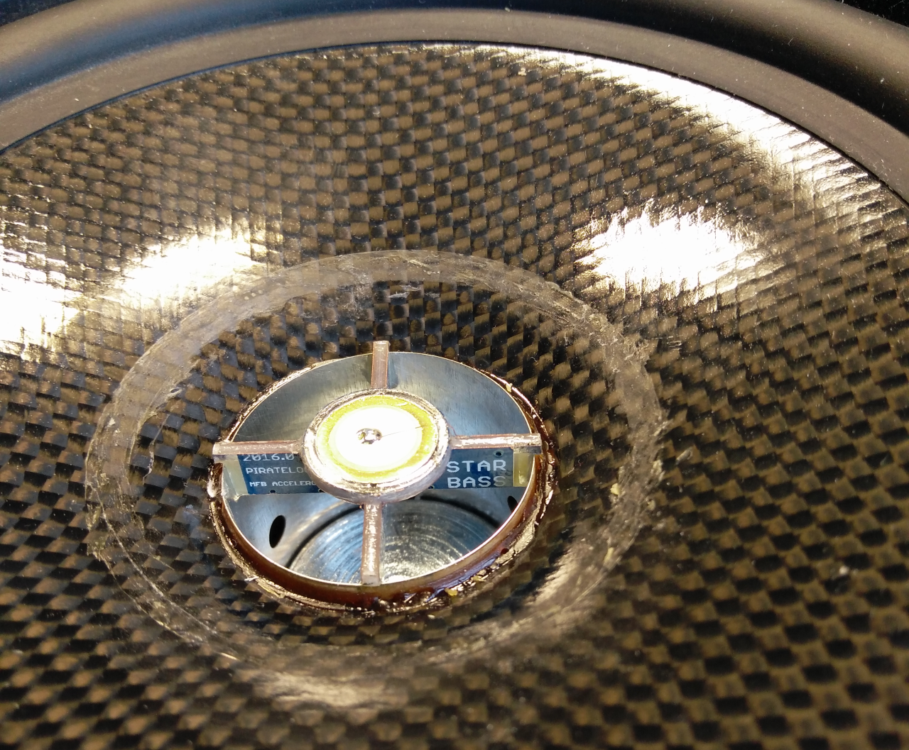
Back in 2017 EVE got originally developed as a quick and dirty solution to add servo bass functionality to an ADAM A7 monitor in conjunction with a StarBass IV accelerometer equipped woofer. EVE 2020.0 basically follows an identical setup with the quick and dirty parts removed and has been optimized using input from this diyaudio thread to improve both its performance as well as its ease of implementation.
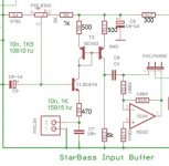
EVE schematics:

PCB layout, board dimensions 50x50mm:

PCB top component layer

PCB bottom component layer - names:

PCB bottom component layer - values:

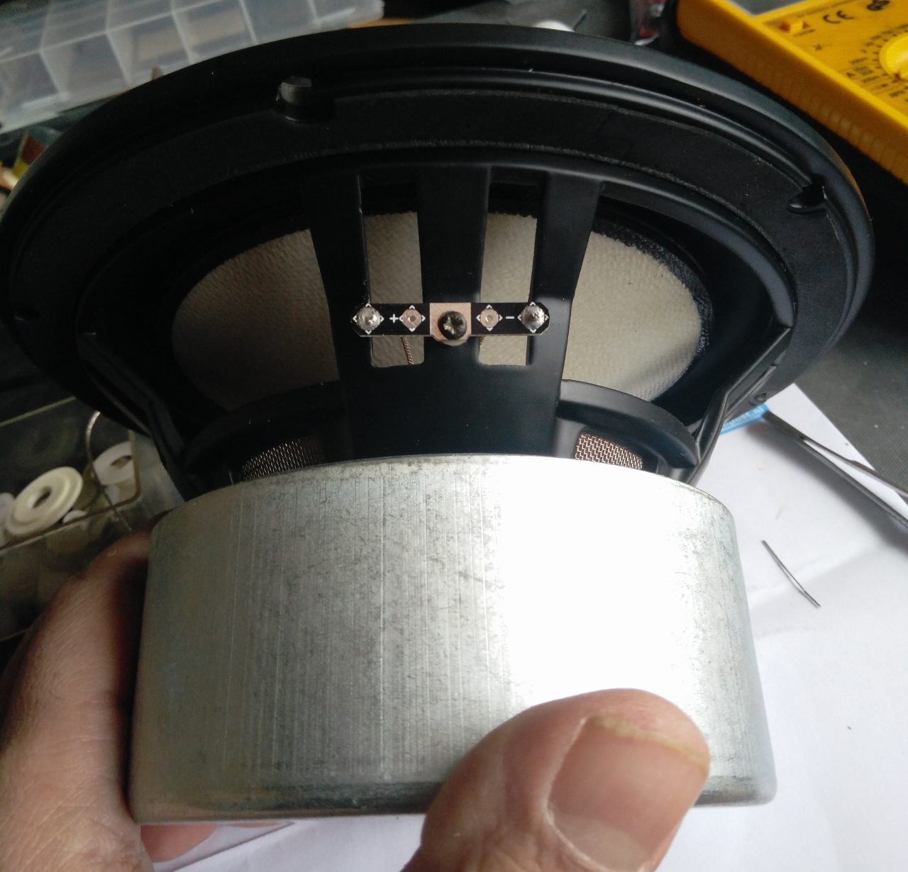
StarBass V accelerometer:

StarBass ClingOn accelerometer:

For availability of both StarBass accelerometers and bare EVE pcb's please see the manual :
https://piratelogic.nl/data/docs/products/eve/piratelogic.eve.2020.0.manual.en.pdf
DIYaudio build threads:
EVE schematics:
PCB layout, board dimensions 50x50mm:
PCB top component layer
PCB bottom component layer - names:
PCB bottom component layer - values:
StarBass V accelerometer:
StarBass ClingOn accelerometer:
For availability of both StarBass accelerometers and bare EVE pcb's please see the manual :
https://piratelogic.nl/data/docs/products/eve/piratelogic.eve.2020.0.manual.en.pdf
DIYaudio build threads:
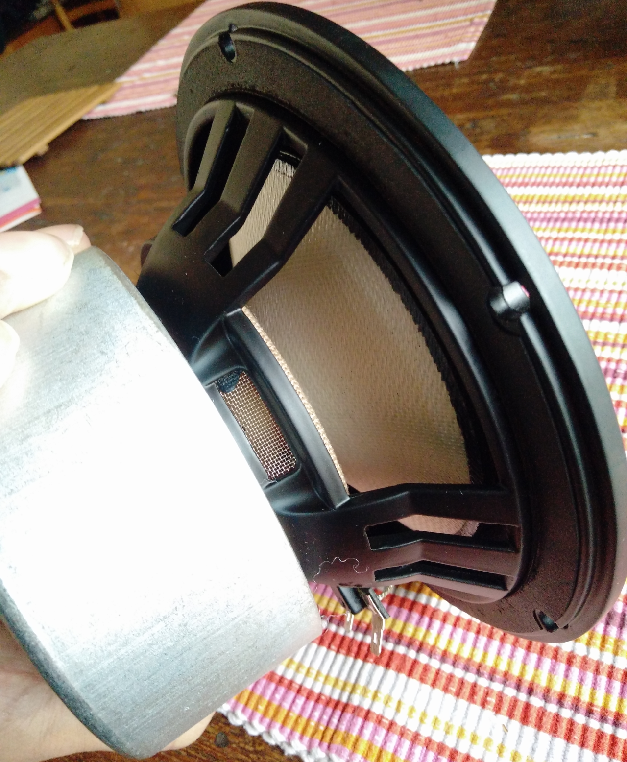
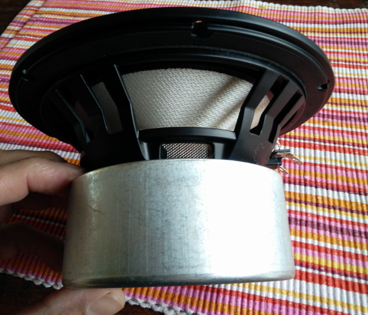
I´m currently using ACH-01 and wonder if the sensor or the break up in the cone is the limitation for low distortion. I will increase the number of drivers (but only use one with motional feedback).
I guess you (Chris) are scanning the market for the best suitable accelerometers out there.
Is there sensors that will suit midrange elements? Or would the non linearity in the sensor be of greater magnitude than the driver itself?
I guess you (Chris) are scanning the market for the best suitable accelerometers out there.
Is there sensors that will suit midrange elements? Or would the non linearity in the sensor be of greater magnitude than the driver itself?
EVE.2020 and ACH-01
I measured PXE input voltage that feeds the ACH-01 and J310 FET. And i got only 2,15 Volts with the Bias Pot at max when ACH-01 was connected.
Strange since it should only consume approx 60uA according to the supplier.
Voltage at Pin 2 is >6 volts when not connected..
I wanted at least 6 volt (half the supply voltage i assumed) when connected so back to the Weller.
Decreased R9 by stacking another 0805 1k resistor on top to 500ohms and got 2,7 volts.
I measured the supply voltage after R17 and it was 7volts, oops.
I stacked R17 with 680ohms and got 400ohms, and get 3,7 volts!
Great, now i started to get a tiny little output on the scope.
Then i decreased R6 from 4,7k ohm to 820 ohms by stacking with 1k ohm and gained 0,8 volt to 4,5 volts. 🙂 slowly making progress, and i was regretting why i did not buy Cling On? Well well.
I stacked another 680ohms to R17 and get 250 ohm 1k//680//680 i ended up with 3 stacked 0805 resistors and 5,3 volts on PXE in
Finally i tuned the current mirror T2 by changing R8 and R11 from 1k each to 500 ohm, guess how.
Now i can regulate the bias voltage between 2,45 and 5,82 Volt and i think i will stop there.
My question is why the big voltage drop when connecting ACH-01?
Attachments

I published measurements of 22dB reduction of THD in another thread in october, and my goal with new PCBs (EVE 2020) and better components break that "record".
Just want to tell the sceptics of MFB. More data to come 🙂
Just want to tell the sceptics of MFB. More data to come 🙂
Never ever use a ceramic capacitor for C9! It is highly microphonic and will cause you problem, been there done that.
Motional Feedback Dipole Subwoofer with a current amplifier?
post 27
And i was playing louder with the servo so the reduction was even better. More measurements later this week.
post 27
And i was playing louder with the servo so the reduction was even better. More measurements later this week.
Could you show the full pictures instead of just the legenda of REW, preferably including both open plus closed loop?
I think he is referring to the Adam A7 which formed the basis for the EVE development back in 2017 in conjunction with an early StarBass III prototype accelerometer:????
The idle current for the ACH01 is much lower then with the starbass series due to the usage of a higher Rsource.My question is why the big voltage drop when connecting ACH-01?
Last edited:
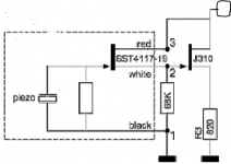
I also built the sensor interface with J310.
I adjusted some values that can be used for ACH-01.
Then there is an issue with DC on the output.
I solved it by adding 3,3 uF on the open loop jumper, and increasing R25 and R26 to 47k Ohms not to disturbing the phase margin at low frequency.
The DC output comes from IC3A and the stage before that.. baybe a DC bias potentionmeter would be handy.. well a cap works..
I have some strong spotlights over my working bench, and the LED+ and LED- in the feedback loop for preventing too high signals (compressor) to the amplifier, they act as a photocell! so if the LEDs in is not getting the same amount of light they interfere with an extra bias voltage over IC3B 😱
It took some time to figure out that also... looking at my scope i saw some DC voltage coming and going while I fiddled around on the board. I ended up painting them! If you put the electronic in a box you will be just fine.
Thanks Chris for your awesome support! Your contribution to the MFB community is of great importance! I think you have started something big!
Attachments
- Home
- Loudspeakers
- Subwoofers
- Piratelogic EVE servobass module