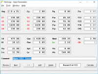
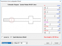
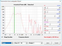
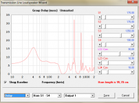
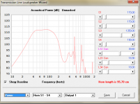
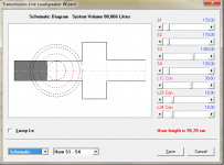
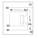
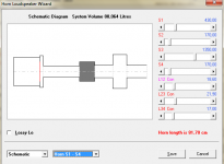
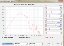
I came across this curiousity while fooling around with Hornresp to see if the out-of-band "noise" in a 4th order BP system can be further reduced. Note that the passband response is not optimized (it's late here and I have to go to bed), but the resulting response looks a bit like a wide-band 6th order BP system - except that the chamber to the rear of the driver is sealed, not vented. I've attached the Hornresp inputs, the simulated response curve, and how such a design can be implemented (the drawing is not to scale).
So, is this a 4th or 6th order system? The response curve and impedance curve suggest 6th, but the driver is in a sealed chamber...
So, is this a 4th or 6th order system? The response curve and impedance curve suggest 6th, but the driver is in a sealed chamber...
Attachments
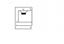
I think it depends on whether section S3-S4 has got a significant length and therefore acts as a chamber or a side branch resonator. It it if the former, the box is a 4th order bandpass + extra 2nd order lowpass (volume S3-S4, port S4-S5). It is similar to how an extra chamber and port turn a 6th order bandpass into an 8th order bandpass.
If S3-S4 has a small length but large cross sectional area, it looks like a 4th order bandpass with a (side branch) resonator midway along the port. That can be useful to dampen the first parasitic port resonance.
If S3-S4 has a small length but large cross sectional area, it looks like a 4th order bandpass with a (side branch) resonator midway along the port. That can be useful to dampen the first parasitic port resonance.
Last edited:
That is cool - and hornresp's Loudspeaker Wizard indicates some damping there might help.
Your example will scale decently @ 0.67X with MCM 55-2421.

Your example will scale decently @ 0.67X with MCM 55-2421.
Last edited:

Playing with damping, with low qts motor, this kind of alignement can gives a flat bandwith with constant GD bandwith in upper band -ie equivalent to a time delay. I tweak sliders looking at delay curve instead of response curve. It works well. As shown in the picture of this post.
(Click on the arrow to see post)
Thanks for the layout idea. It lead me to this one.
Wow, that's some impressive out-of-band noise suppression going on there. My vacation starts next week - I think I'll spend some of it putting together a workbook or two that can be used to fold these creations into a box.
The best feature seems to be the constant GD that gives on it bandwith only (16ms spike - 7 ms constant GD) = 9ms GD max at 40hz.Wow, that's some impressive out-of-band noise suppression going on there. My vacation starts next week - I think I'll spend some of it putting together a workbook or two that can be used to fold these creations into a box.
It gives constant time delay in exchange of high order low pass, while allowing low order high pass.
It just require adding ~7ms delay as starting point on others ways, wich is below enough the 9ms allowed by minidsp&co.
Note it's a 0,22 qts woofer, with some inductance ( lossy Le model not used in sim), a typical strong motor as B&C's for exemple.
The sim is slightly inaccurate though, as you have the driver side-firing into Vtc, which means that there's going to be an offset effect not accounted for in the sim. I don't think it will affect the LF passband too much, if at all, and with some careful engineering of the layout, it could perhaps be used to null out one of the remaining out of band peaks in the response curve.
Hornresp is enough to work on gross layout. Akabak is indeed needed for fine tuning this king of simulation, but i personally still have hard time with stuffing in Akabak.The sim is slightly inaccurate though, as you have the driver side-firing into Vtc, which means that there's going to be an offset effect not accounted for in the sim. I don't think it will affect the LF passband too much, if at all, and with some careful engineering of the layout, it could perhaps be used to null out one of the remaining out of band peaks in the response curve.
Last edited:
You guys are KILLING It with the new features in HR! Excellent OUT OF THE BOX thinking!
It make me want to ask again a new feature ^^
If we could have l23, l34 in hornresp switchable as stub instead of con/par/exp SIM would be right. I didn't manage to convince David on my own^^
Sorry, I got the paternity the 26th March 2019, 04:23, lol.
EDIT : in fact, as long as we don't know if David should implemente side branch absorber (big thanks to Freddi suggestion), we only have approximation sim with serie chambers instead of side branch chamber. Of course, it could be done with akabak, but tuning volume is a pain with it, if remember that there's some weird difficulties about duct VS pressure chambers, and stuffing is not as easy as with hornresp.
On a side note, a funny thing to do is to play with this closed back arrangement in hornresp with wavefront simulator.
click on the arrow link
EDIT : in fact, as long as we don't know if David should implemente side branch absorber (big thanks to Freddi suggestion), we only have approximation sim with serie chambers instead of side branch chamber. Of course, it could be done with akabak, but tuning volume is a pain with it, if remember that there's some weird difficulties about duct VS pressure chambers, and stuffing is not as easy as with hornresp.
On a side note, a funny thing to do is to play with this closed back arrangement in hornresp with wavefront simulator.
Last edited:
Note : The closed back 2 front chamber bandpass can be simulated too using 8th order bandpass wizard and simulating a closed back with a 0,01cm² port of few cm. It helps tuning port size using port velocity charts. It's first hard to understand that ports don't show the same velocity Vs frequency curves, until played with wavefront simulator.
We cannot export stepped segment sims from hornresp, but it's not that exporting non stepped sim and modifying script numbers to make it stepped. And David is actually working on a more appropriate tool in Hornresp to sim those absorbing chambers than using stepped segments.
What do you have in mind that hornresp cannot do ?
Plotting vent port velocity ? Effect of adding time delay + filtering on step impulse ?
What do you have in mind that hornresp cannot do ?
Plotting vent port velocity ? Effect of adding time delay + filtering on step impulse ?
- Status
- Not open for further replies.
- Home
- Loudspeakers
- Subwoofers
- Interesting new bandpass alignment...?