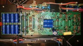
I have one on the bench... well covering most of the bench actually.
It was tripping the breaker at the panel. The right channel was the culprit. I changed out all of the finals in that one section that was suspect because three of them were dead shorted. Also changed out the pre drivers for that section too because one of them was shorted. No more tripping breaker. The right channel seems to be ok now... passing audio all the way through anyway.
When I power it on there is a delay before the output relays engage. They stay latched and I was able to adjust the bias and DC offset for the right channel. However, when I tried to adjust either the bias or DC offset for the left channel I notice that the trimpots will do nothing. The bias at the final outputs starts out a little under-biased and runs up to a reasonable level. It runs up to bias quickly then after about 20 seconds or so peaks out and starts to go back down slowly... It reminds me of watching filter caps drain through a bleeder resistor. The bias will go all the way down to zero if you wait long enough. All three output sections of the left channel do this. The right side seems to be fine. Also, the output relays stay engaged. The 39v plus and minus voltages seem fine as do the 80v plus and minus.
I have pulled every semiconductor device on the driver board in hopes of finding something open or faulty but to no avail. I did change several of the devices, mainly some MJE15030 and an MJE15031. I changed out the 39 volt zeners too. I pulled all of the outputs for both channels and replaced the silipads with Wakefield and mica insulators... All of them were tested using an Atlas Pro DCA 75. They are not exactly balanced, but neither side's outputs was much more in or out of balance than the other. So If the right side is working...
I swapped the trimpots to the opposite side of the left channel board so that I could try it on the right channel. The board seems to contain the malfunction because it does the same thing when connected to the right channel. I guess i could swap the trimpots over on the right channel board and see if it would work with the left channels outputs. 😡
What am I missing? I am totally stumped here!! This is a behemoth of an amp and swapping known-good parts from right to left or vice-versa is a lot easier said than done. Does anyone here have any experience with these units?
I have attached the service manual that I have been using although it doesn't seem to contain all of the correct drawings... for example, what are the two trimpots on the protection board meant to control? The ones marked R and L on the board itself... I see no trimpots in the SM schematics. As a further note... I pulled those trimpots so i could adjust the one marked L to the same value as what was working on the one marked R.. roughly 10-11Ω. This also made no difference.
I have no hair left to pull out... please help!!
Attachments
Can you get to the emitter and collector of Q20 and measure the voltage? Does it stay put where you set it? Or does it vary with warm up? Are the base and collector Q21 actually connected? I can't see any correlation between bias and DC offset, yet.
Craig
Craig
I haven't looked at the schematic....
Start looking at the board itself. Ohm the traces; left vs right. Especially top to bottom looking for broken vias. You've eliminated most everything else.
Start looking at the board itself. Ohm the traces; left vs right. Especially top to bottom looking for broken vias. You've eliminated most everything else.
E to C at Q20 = 2.67v.
Yes the B and C are connected at Q21, I even pulled the solder again just to confirm.
I will check continuity through the traces and reflow on the top side just to confirm connection.
Thanks for the help guys! I don't feel so bad due to your comments and suggestions.... much appreciated!!
Yes the B and C are connected at Q21, I even pulled the solder again just to confirm.
I will check continuity through the traces and reflow on the top side just to confirm connection.
Thanks for the help guys! I don't feel so bad due to your comments and suggestions.... much appreciated!!
- Status
- Not open for further replies.