Hi there DIY audio folks,
I'm looking to make a compact horn loaded mid bin using a pair of 15" 18sound 15nd930's to use with a PA sound system that I built last year. Design goals are to match the 100db sensitivity of the rest of the system (4x 15" FLH subs and 2x 2 way synergy horn tops), to help lower the crossover point between the tops and subs and subsequently help flatten out our response in the 100-300hz range. Also looking to have them relatively compact so they can sit on pole mounts with the synergies strapped on top for when we do outdoor events and cluster the subs in front of the stage.
Small parameters of the driver are as below
18sound15nd930
Sd=850.00
Bl=22.99
Cms=2.00E-04
Rms=4.17
Mmd=83.47
Le=1.61
Re=5.50
Pmax=100
Xmax=5.0
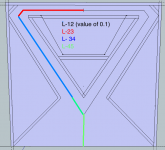
I'm not at that stage with my knowledge of audio that I can glance at a bunch of small parameters and identify what kind of cab the driver is best suited to. But I had a look around and found this layout in a thread (http://www.diyaudio.com/forums/pa-systems/241890-need-help-midbass-horn-2.html post no 14) and thought it would be worthwhile seeing if I could model it, or something like it, to see how the driver would play in it.
My only experience so far with horn resp is a simple tapped horn project recycling an old driver and plate amp for my home music system. I've had a go at deducing the modelling for this new cab but have some questions.
I'll attach a photo of a sketch up file I have been using to help me figure out what cabinet design can work.
1) I'm not sure what driver arrangement to model this cab as. For the moment I have been using the 'normal' nd arrangement.
2) My thoughts on what constitutes the horn segment length parameters for the L12,23 etc are shown in the sketch up picture- are they based on correct assumptions?
3) because the horn path goes in two directions for the first few sections of the horn, does that impact the parameters I put into horn resp? Ie: for the value of s1 do I need to double the actual distance between the baffle and the rear panel?
If you have any comments or suggestions for me- i'm all ears! If you know of another cab style that would better suit my needs then let me know. I'm not asking for people to do the design work for me- I'm keen to learn myself. However if I'm completely on the wrong track then save me some time.
Thanks!
Mark
I'm looking to make a compact horn loaded mid bin using a pair of 15" 18sound 15nd930's to use with a PA sound system that I built last year. Design goals are to match the 100db sensitivity of the rest of the system (4x 15" FLH subs and 2x 2 way synergy horn tops), to help lower the crossover point between the tops and subs and subsequently help flatten out our response in the 100-300hz range. Also looking to have them relatively compact so they can sit on pole mounts with the synergies strapped on top for when we do outdoor events and cluster the subs in front of the stage.
Small parameters of the driver are as below
18sound15nd930
Sd=850.00
Bl=22.99
Cms=2.00E-04
Rms=4.17
Mmd=83.47
Le=1.61
Re=5.50
Pmax=100
Xmax=5.0
I'm not at that stage with my knowledge of audio that I can glance at a bunch of small parameters and identify what kind of cab the driver is best suited to. But I had a look around and found this layout in a thread (http://www.diyaudio.com/forums/pa-systems/241890-need-help-midbass-horn-2.html post no 14) and thought it would be worthwhile seeing if I could model it, or something like it, to see how the driver would play in it.
My only experience so far with horn resp is a simple tapped horn project recycling an old driver and plate amp for my home music system. I've had a go at deducing the modelling for this new cab but have some questions.
I'll attach a photo of a sketch up file I have been using to help me figure out what cabinet design can work.
1) I'm not sure what driver arrangement to model this cab as. For the moment I have been using the 'normal' nd arrangement.
2) My thoughts on what constitutes the horn segment length parameters for the L12,23 etc are shown in the sketch up picture- are they based on correct assumptions?
3) because the horn path goes in two directions for the first few sections of the horn, does that impact the parameters I put into horn resp? Ie: for the value of s1 do I need to double the actual distance between the baffle and the rear panel?
If you have any comments or suggestions for me- i'm all ears! If you know of another cab style that would better suit my needs then let me know. I'm not asking for people to do the design work for me- I'm keen to learn myself. However if I'm completely on the wrong track then save me some time.
Thanks!
Mark
Attachments
your specs dont appear to match the product sheet found here
0010 15ND930 - 15ND930 : Eighteen Sound - professional loudspeakers
0010 15ND930 - 15ND930 : Eighteen Sound - professional loudspeakers

I would be really very careful of putting those on a stand with something else on top.
I'm using some fairly good quality stands (40kg rated), and I wouldn't go much further than what I'm doing now with them: Fane 500w midbass with an EV DH1a sat on top on a wooden frame. Probably 28kg for the lot, but the centre of mass is high.
If you're set on putting your kicks on stands, make sure you simulate in 4pi. IMO, having them on the floor would be better - its safer rigging, and you'll get a couple of dB output for free.
It might be of interest to you to know that Nexo does something similar to what you're after in their Alpha system: the B1 kickbin is a front-loaded horn with a compression chamber, which pushes the tuning down a bit. Might be worth a look. IIRC they get 80-250Hz out of it, but they can go down to 40Hz before giving up completely.
Chris
@ Chris- We have a good set of 60kg rated tripods with a large spread on the legs. The synergy horns don't weigh much either so I don't think we should have much of a problem. We want to keep the kick bins close to the synergies for the sake of imaging- more important to us than a few free DB from boundary loading. The best option for us would be to convert our synergies to 3 ways with some extra woofers but that probably wont happen for a while. For out current situation It looks to be easier to make some small kick bins until we can get that project off the ground. Thanks for the heads up on the Nexo bins. Will have to give them a look!
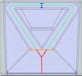
Ok here is take two on understanding how to think of this cab in terms of horn resp parameters.
On advice from GM there are now just two horn expansions (does the fact that the driver baffle is flat and does not 'see' any expansion at all cause an issue when modelling it this way?) the green line now constitutes L12, The red line L23. Now that we are considering both horn paths of the green line constitute L12, does that mean I need to double the value of S1? (blue dimension). Orange dimension is S2, and purple line is S3.
Your patience and advice is very much appreciated by this noob!
Mark
Attachments
- Status
- This old topic is closed. If you want to reopen this topic, contact a moderator using the "Report Post" button.
- Home
- Loudspeakers
- Subwoofers
- A little help: 100-300hz Mid bin using 18 sound 15nd930