Hi,
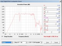
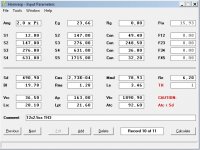
I was playing with hornresp to find what to do with a 12" 7mm xmax for home use, aiming for 115db 2pi (only for headroom !) with 23V, and trying simple compound horn, closed rear chamber, 6 order bandpass, or tapped horn, i was more or less always getting the same results around 150 liter, but low bandwith.
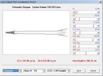
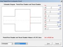
So i came to mix things, adding 3 more sections to the tapped horn adding a back chamber, and a "output" ported chamber.
I came to something interesting, a bit hard to get, but i managed to do this twice with two speakers. Hard to tune the chamber, and adjust the stuffing, but it should be really interesting if it work as well as it sims.
It's myabe a bit like the transflex design, but with normal mouth, simulated with hornresp, and, in a high efficiency (and so big volume) version.
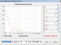
It's not totally flat, need lot of stuffing at L12, and got a big dip in response, but from what i've seen on this forum, it's still seems reaaally interesting.
1/5 compression ratio is a lot, and should be not so much a problem since 115db aim is only for headroom ^^
I did not tryed Akabak yet. But i suspect those kind of design really harder to find than with hornresp sliders.
All comment, and advices welcome !
I was playing with hornresp to find what to do with a 12" 7mm xmax for home use, aiming for 115db 2pi (only for headroom !) with 23V, and trying simple compound horn, closed rear chamber, 6 order bandpass, or tapped horn, i was more or less always getting the same results around 150 liter, but low bandwith.
So i came to mix things, adding 3 more sections to the tapped horn adding a back chamber, and a "output" ported chamber.
I came to something interesting, a bit hard to get, but i managed to do this twice with two speakers. Hard to tune the chamber, and adjust the stuffing, but it should be really interesting if it work as well as it sims.
It's myabe a bit like the transflex design, but with normal mouth, simulated with hornresp, and, in a high efficiency (and so big volume) version.
It's not totally flat, need lot of stuffing at L12, and got a big dip in response, but from what i've seen on this forum, it's still seems reaaally interesting.
1/5 compression ratio is a lot, and should be not so much a problem since 115db aim is only for headroom ^^
I did not tryed Akabak yet. But i suspect those kind of design really harder to find than with hornresp sliders.
All comment, and advices welcome !
Attachments
Last edited:
Your first schematic looks ready for launch
😛
Dave
Tripoli Rocketry Association # 07694
NAR #77672
😛
Dave
Tripoli Rocketry Association # 07694
NAR #77672
Cool result. What driver is that? 4 octaves is wide but technically you have a narrow cancellation null at 80Hz that is about 10 to 15Hz wide - it may not look so narrow in reality and end up with quite a dip there. The rest of the output is probably acting in the FLH (bass horn regime) as you are beyond the tapped horn null. I could try this in Akabak and see what it looks like.
Looks like a 12" with pretty strong motor and heavy cone.
If lighter and lower Le driver is used, it might extend even higher.
If lighter and lower Le driver is used, it might extend even higher.
If it's hard to dial in in a sim it's going to be 10x harder to dial in in a build. Shift the t/s parameters just a bit and see if the response stays pretty. Add a bit of Re to simulate power compression and see if it holds.
The more complex the box gets the more t/s parameters (and shifting parameters) can affect it so as always it's best to measure t/s yourself, not use published specs.. You might have to tweak a bit to get the desired response when you build it, and response might change under heavy load.
The more complex the box gets the more t/s parameters (and shifting parameters) can affect it so as always it's best to measure t/s yourself, not use published specs.. You might have to tweak a bit to get the desired response when you build it, and response might change under heavy load.
Also it doesn't appear to have much advantage over a simple ported box of less than half the size. Here's your design (150 liters) compared to a small ported box (58 liters), both at xmax. The ported box response issue from 300 - 600 hz could be straightened out fairly easily with a bit of stuffing and port / driver location tweaks so the ported box could have just as much bandwidth as your design (if not more). I wasn't interested in extending the response (although it's fairly simple to do) just comparing spl at xmax here. You design will have less port compression and power compression to be sure but I'm not sure the extra complexity is worth the bother.
Also the high compression ratio and bringing the horn to a point at the closed end might be hard on the driver, it's an easy ride for the driver in the ported box. And it's going to be tough to fire a 490 sq cm driver into a 92 sq cm throat chamber. You could do it with an adapter plate but that's needless complexity. And if you are building from sheet wood with 2 parallel sides and 2 expanding sides you need to switch to PAR segments (although only the segments that have cross sectional area changes will be affected and it only amounts to about 3 liters difference). Just little things to look out for.

Also the high compression ratio and bringing the horn to a point at the closed end might be hard on the driver, it's an easy ride for the driver in the ported box. And it's going to be tough to fire a 490 sq cm driver into a 92 sq cm throat chamber. You could do it with an adapter plate but that's needless complexity. And if you are building from sheet wood with 2 parallel sides and 2 expanding sides you need to switch to PAR segments (although only the segments that have cross sectional area changes will be affected and it only amounts to about 3 liters difference). Just little things to look out for.
Last edited:
Since it's a cheap driver , i don't trust parameters, and i'll measure them. But, it's a starting point, and managed to do so with another driver. Sinus waves test show me that with this driver suspension is a bit noisy, so i first looked at a 6th order bandpass box.
The fact is that i only got 75-150w amps, but it's composite bridged amps that use remote sensing (4 wire to speaker) with damping factor > 1500 below 500hz...
The speaker is still rated 250w, so i should be far from power compression. So i gives me free headroom compared to bass reflex, and funny challange ^^
If i decide to do it, it will be a long time project. It should be done with composite sheet (3mm hardwood mdf like / 30mm foam / 3mm normal mdf). I'd like to make it as a active fullrange tower of ~ 150 x 40 x 40 cm, with 2 xkhi with 4" driver, and one dome tweeter. The more complex, the more challanging it is, even if it's stupid ^^
As said earlier, i've not for the moment tryed AkAbak, but i know i'll have to 🙂Cool result. What driver is that? 4 octaves is wide but technically you have a narrow cancellation null at 80Hz that is about 10 to 15Hz wide - it may not look so narrow in reality and end up with quite a dip there. The rest of the output is probably acting in the FLH (bass horn regime) as you are beyond the tapped horn null. I could try this in Akabak and see what it looks like.
Sorry for flood, i cannot re-edit...
Compression ratio of chamber can be reduced to 3,5 in the exange of a bit mid extension, and higher Q dip...
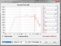
Just to show, here a sim (1) with same kind of box, with a 10" 13,5mm xmax with less powerfull motor (qts=0,35). I suspect it needs a very powerful motor.
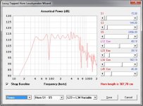
And another pretty sim (2) with the lovely carbon fiber cone bms 12s305 ("only" 180€) => max output @xmax=11mm 122db /150L / 350w@8ohm/ /50V 40-700hz @-3db
Compression ratio of chamber can be reduced to 3,5 in the exange of a bit mid extension, and higher Q dip...
Just to show, here a sim (1) with same kind of box, with a 10" 13,5mm xmax with less powerfull motor (qts=0,35). I suspect it needs a very powerful motor.
And another pretty sim (2) with the lovely carbon fiber cone bms 12s305 ("only" 180€) => max output @xmax=11mm 122db /150L / 350w@8ohm/ /50V 40-700hz @-3db
Attachments
Last edited:
So i gives me free headroom compared to bass reflex...
My sim suggests it doesn't - a bass reflex of less than half the size is just as loud.
Anyway I see you disregarded just about all of my notes and even added an EXP segment - good luck building that.
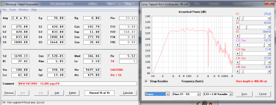
Lol...the Exp is just a mistake. And it's only on a sim, for fun with a 21" !
Please, just a guy, take time to read. I've already seen how knowlegable you are. Your advice are all correct, i understand each. My case of use is specific since i want to use 23 V amp. There's nothing free, twice the efficience, twice the size ! ^^
I've just finished a very low efficience speaker a short while ago with a 10" sub that take 44V, for a friend. Works great. But here the exercice is about efficiency.
I'm not trying to find the best sub of the world. It's only a variation, interesting effeciency wise (not loosing bandwith).
The 21" precision devices with 600w sims well, staying far from power compression. I'm not saying that is the best of the best solution. It's only a variant that is interesting from a point of view.
About RE and power compression, there's not problem with such efficient design, since it require for example HALF the power of the bass reflex you suggested. HALF.
And i've tell about the use of remote sensing amp, 4 wire to speaker, so no wire resistance virtually, preserving enormous real damping factor.
And it's just a sim, on a forum...not claming for anything, if sharing...
For the moment, i would be pleased if i came to built it someday, but it's only sim. It need a lot more involvement since i start building.
EDIT : You've already advised somwhere else about PAR segment, I think i start to understand , so need more work, thanks !
Last edited:
My case of use is specific since i want to use 23 V amp. There's nothing free, twice the efficience, twice the size ! ^^
Ok, I get it, if that's the only amp you have efficiency is important. Sorry.
The BADASS-BANDPASS! =D
PapaSteack ,
I had happened across this sort of alignment a few times while experimenting with hornresponse and i just recently recreated it in Akabak as well ...Great output from this type of bandpass alignment but cone control isn't quite as good as some designs , it could be great in a situation like your's where you don't plan on slamming the driver to it's full thermal capacity, which means you would also benefit from less thermal compression , in theory at least 😀
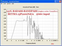
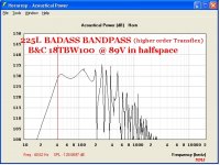
It is either an 8th order bandpass (from a TH perspective) or a type of parallel tuned 6th order with a tapped feature, it all depends on how you look at it i suppose, nevertheless the simulation shows lots of promise with drivers that have strong motors ... I had tried drivers like the Eminence Definimax4012 , Beyma 15P1200Nd/N , and B&C 18TBW100 with some exciting results in a reasonably sized package ... ...I posted about it a few times in the Transflex discussion , here is one post: http://www.diyaudio.com/forums/subw...ld-series-tuned-6th-order-66.html#post4046976
😛 I call it the "BAD/\SS-BANDPASS" ..
I was never able to get the kind of outrageous bandwidth that you are getting in your sims, probably because i was just using straight pipe segments to keep things simple ..... It looks like you have taken things a step further with flares/expansions ... Good Job Man 🙂
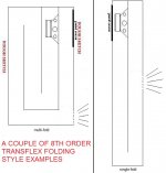
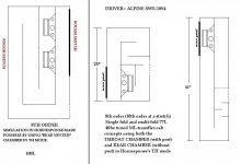
I will attach a few graphs and ideas for folding schemes that i came up with, and as you can see the bandwidth is just mediocre (compared to what you have going on) but the output is excellent and the build is simple =)
I have a few old blown Definimax 12s here, if i ever get them reconed i might try this design but i have to get my Karlflex cabs built first, time for me to stop lollygagging and dilly-dallying with sims and get to work ..
PapaSteack ,
I had happened across this sort of alignment a few times while experimenting with hornresponse and i just recently recreated it in Akabak as well ...Great output from this type of bandpass alignment but cone control isn't quite as good as some designs , it could be great in a situation like your's where you don't plan on slamming the driver to it's full thermal capacity, which means you would also benefit from less thermal compression , in theory at least 😀
It is either an 8th order bandpass (from a TH perspective) or a type of parallel tuned 6th order with a tapped feature, it all depends on how you look at it i suppose, nevertheless the simulation shows lots of promise with drivers that have strong motors ... I had tried drivers like the Eminence Definimax4012 , Beyma 15P1200Nd/N , and B&C 18TBW100 with some exciting results in a reasonably sized package ... ...I posted about it a few times in the Transflex discussion , here is one post: http://www.diyaudio.com/forums/subw...ld-series-tuned-6th-order-66.html#post4046976
😛 I call it the "BAD/\SS-BANDPASS" ..
I was never able to get the kind of outrageous bandwidth that you are getting in your sims, probably because i was just using straight pipe segments to keep things simple ..... It looks like you have taken things a step further with flares/expansions ... Good Job Man 🙂
I will attach a few graphs and ideas for folding schemes that i came up with, and as you can see the bandwidth is just mediocre (compared to what you have going on) but the output is excellent and the build is simple =)
I have a few old blown Definimax 12s here, if i ever get them reconed i might try this design but i have to get my Karlflex cabs built first, time for me to stop lollygagging and dilly-dallying with sims and get to work ..
Attachments
-
 BADASS-BANDPASS-HIGH-ORDER-TRANSFLEX-BEYMA15-66V-137L.JPG155.8 KB · Views: 218
 -
 BADASS-BANDPASS-HIGH-ORDER-TRANSFLEX-18tbw100-89v-halfspace.JPG160.6 KB · Views: 214
 -
 8TH order Transflex-- ORDER-ROUGH SKETCH--2.JPG55 KB · Views: 226
 -
 8TH-or10th order-- ORDER-ROUGH SKETCH--2.JPG57.9 KB · Views: 222
 -
 QUASI-8TH ORDER-ROUGH SKETCH.JPG19.8 KB · Views: 216
Last edited:
Trying a lot of sims, i realised fast that it seems to need a qts below 0,3 to get highest bandwith excusion, and even with 0,27 my driver is not ideal, so Eminence Definimax4012 , Beyma 15P1200Nd/N , and B&C 18TBW100 are maybe a bit lacking of motor from this point of view.
As JAG pointed, "my design" need a adapter because of the small ATC, that seems, as XRK told, to transform the whole thing acting in front load horn from the back of the TH.
Trying to measure thiele parameters yesterday, attaching weight on the cone, it revealed that the dome of the cone is a lot more fragile than the rest of the cone. It should maybe benefit of adding a bit of glass fiber/PVA glue (i don't want to spend money on resin for this stuff), if it don't change too much parameters.
I didn't managed to measure impedance with rew for thiele parameters with headphone level output even "boosting" it with "the wire" headphone amp (cause i built it without gain ^^). I need to add some gain circuit before, so i plan to use TI volume control board to get some gain, and measure. And I don't have other good non-bridged amp to do the trick.
- Status
- Not open for further replies.
- Home
- Loudspeakers
- Subwoofers
- 4 octave Tapped Horn Variant (hornresp sim in ^^)