Hi all,
I project to build a 3-way OB (planar) approx. 24"W and 62"T; I post in the subwoofer forum because I wish to know where I have to place the eight 5" subwoofers (fs 45hz fx 300hz) I'll use in order to get the max spl in the low range...? i.e. randomly on the full area, or more on a broken vertical line?
I thought something like this:
Does it exist any rule?
Thanks!
I project to build a 3-way OB (planar) approx. 24"W and 62"T; I post in the subwoofer forum because I wish to know where I have to place the eight 5" subwoofers (fs 45hz fx 300hz) I'll use in order to get the max spl in the low range...? i.e. randomly on the full area, or more on a broken vertical line?
I thought something like this:
An externally hosted image should be here but it was not working when we last tested it.
Does it exist any rule?
Thanks!
Assuming an 8 ft (96") ceiling and (8) drivers equates to (9) 10.66" spacings or ~1/4 WL apart at 317.8 Hz, so a 300 Hz XO is theoretically marginal, but being an 'infinite' array where you'll be in the near-field, it shouldn't be an issue.
Considering you're using a single point source mid and tweeter though, clustering the woofers in a circle around them to create a very large virtual point source is what me and some others have done with excellent results.
If for space reasons this isn't viable, then mounting the woofers butted up against each other and mounted on a concave curved baffle with it focused at the listening position is acoustically similar.
Anyway, some options to mull over and if not too much cost/hassle for you, best to try one of each to see what works best in your room as each interacts very differently.
GM
For maximum LF output of the subwoofers a narrow mounted
cluster near the bottom and a foot/stand for the baffle that
is tight (foot of same width as the baffle) against the bottom
is the best solution.
(Strong) asymetrical mounting is preferable.
You can use the program "edge" from Tolvan data for
rough simulation. The bottom effect can be simulated
by using a mirrored baffle (with same drivers) where
the bottom is the mirror.
Seamless integration of the midranger is a different task ...
The source made up by the woofers should not be too wide
to avoid beaming in the horizontal plane.
My first try would be 2 vertical lines of 4 Woofers each,
which are "crossed" as tight as possible.
O_
_O
O_
_O
O_
_O
O_
_O
Maybe the upper 2 woofers with a larger distance to
get the Midranger in between.
Other possibility is to get the Midranger ontop
of the (double)woofer Line:
This would it make it easier to get tweeter and midrange
close together and the tweeter on the right (ear) height.
WW
.T
.M
WW
WW
WW
.T
.M
WW
WW
WW
WW
Tweeter too high?
.W
.T
WW
WW
WW
WW
A long vertical woofer line array does not fit into the
concept IMO, because your multiway
single midranger/single tweeter
approach goes more towards a point spource.
Kind Regards
Last edited:
Thanks guys for your thoughts!
1) I find the "edge" to be difficult to use, sorry...Even Jeff Bagby's Baffle Edge Diffraction Simulator...
2) Regarding that I want to keep a point-source concept, I understand that I have to surround the mid-driver and tweeter, at least to a certain degree. This will also give me a certain latitude in the fr point and slopes...
GM, as you have experienced such "suroundings", what about cavity effects du to so many cones placed arround the mid driver and tweeter?
So what do you think about this one (tweeter at ears height):
An externally hosted image should be here but it was not working when we last tested it.
Hi crazyhub,
i would prefer midrange and tweeter in a vertical line,
because summation of both will usually be angle dependent.
Normally one should try to avoid those angle dependencies
in the horizontal plane since you may not want to sit
in perfect symmetry to the speakers on your sofa all the time
but want to move little bit. Even then both speakers should
sound as similar as possible.
Concerning the woofer configuration i told my opinion before.
That circular arrangement may work well, but the
geometric extension of the bass source is unecessarily enlarged
compared to wavelength at XO. So the "point source approximation"
is hampered in making the bass source wider than has to be by nearly
a factor of 2 ... directivity of (summed) bass source and midranger
will differ more than necessary in the crossover region.
The woofers could be mounted closer for less beaming.
To have some of the woofers close to the bottom will
positively affect the lower frequency limit which can be reached.
But everyone will build the system of his interest in the
end ... so its just an opinion.")
edit: You could also think about lowpass filtering some of the
woofers at lower XO depending on room situation and Qts of
the drivers. That could be interesting to fatten up the deep bass
and shrink the size of the bass source at XO to the midranger...
Cheers
i would prefer midrange and tweeter in a vertical line,
because summation of both will usually be angle dependent.
Normally one should try to avoid those angle dependencies
in the horizontal plane since you may not want to sit
in perfect symmetry to the speakers on your sofa all the time
but want to move little bit. Even then both speakers should
sound as similar as possible.
Concerning the woofer configuration i told my opinion before.
That circular arrangement may work well, but the
geometric extension of the bass source is unecessarily enlarged
compared to wavelength at XO. So the "point source approximation"
is hampered in making the bass source wider than has to be by nearly
a factor of 2 ... directivity of (summed) bass source and midranger
will differ more than necessary in the crossover region.
The woofers could be mounted closer for less beaming.
To have some of the woofers close to the bottom will
positively affect the lower frequency limit which can be reached.
But everyone will build the system of his interest in the
end ... so its just an opinion.
edit: You could also think about lowpass filtering some of the
woofers at lower XO depending on room situation and Qts of
the drivers. That could be interesting to fatten up the deep bass
and shrink the size of the bass source at XO to the midranger...
Cheers
Last edited:
Hi crazyhub,
i would prefer midrange and tweeter in a vertical line,
because summation of both will usually be angle dependent. OK, even if some off-axis isn't a big issue when listening at some distance...
Concerning the woofer configuration i told my opinion before.
That circular arrangement may work well, but the
geometric extension of the bass source is unecessarily enlarged
compared to wavelength at XO. So the "point source approximation"
is hampered in making the bass source wider than has to be by nearly
a factor of 2 ... directivity of (summed) bass source and midranger
will differ more than necessary in the crossover region. I don't understand your point of view... Assuming the ears are in-axis with mid + tweeter, placing the woofers surrounding these drivers is the best way to limit directivity deviation patterns at Fx, no?
The woofers could be mounted closer for less beaming.
To have some of the woofers close to the bottom will
positively affect the lower frequency limit which can be reached.
But everyone will build the system of his interest in the
end ... so its just an opinion.
edit: You could also think about lowpass filtering some of the
woofers at lower XO depending on room situation and Qts of
the drivers. That could be interesting to fatten up the deep bass
and shrink the size of the bass source at XO to the midranger...That's the tricky part of my hoped design: if I make a vertical line (even ww,ww,ww,ww), directivity patterns don't mate this of the mid-driver, exept if I make two different low-pass on two groups of woofers as you did advise, which I wished not to do at first view.
At this point, I really think to place all the woofers near the bottom in a
ww
www
www
configuration, with a low Fx (200hz) and use a mid-driver that could go low enough...finaly a subwoofer + wide band + tweeter design; in such a way I avoid directivity problems and get a better spl in the bass range...seems to be what I have to do...
An externally hosted image should be here but it was not working when we last tested it.
Cheers
Last edited:
I don't understand your point of view... Assuming the ears are in-axis with mid + tweeter, placing the woofers surrounding these drivers is the best way to limit directivity deviation patterns at Fx, no?
No. Best way to avoid deviation in directivity is to have the both
sources which shall be XOed small compared to wavelength each in itself.
Or at least to have them both in about the same relation to wavelength.
You cannot avoid the bass source to be larger than the midranger,
but cou can keep it as compact as possible.
The bass source in the "circular" approach is not small against
wavelength: It is larger than lambda/2 in both height and width while
the midranger is smaller than lambda/4. That is a big difference in
relation to wavelength.
Addditionally the distance of the drivers to be crossed over has to
be as small as possible compared to wavelength.
To me your last design is a bit extreme in that respect:
Too much distance to the midranger IMO.
The configurations i proposed in my former post are already
compromises between deep bass efficiency (uses the bottom) /
compactness of bass source and small distance from bass to
midranger.
They are not a perfect solution, there are always tradeoffs.
To put cuttoff lower for some of the woofers (near bottom)
might be a way to "harmonize" things.
If you do not want to make simulations you will have to experiment
with the real object. Not the worst way to go ...
Only thing you have to loose is some wood and some hours of
your time ...
edit: Sorry !!!!
I haven't read carefully. With significantly lower XO (90-150 Hz ?)
your last proposal seems very viable to me.
(Needs big coils an caps when implemented as a passive XO)
Have you googled for PLLXO ... ?
And i think there are some "Fullrange And Subwoofer" designs out
there which go a similar way. So you are in good company !
Kind Regards
Last edited:
Hi,
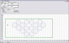
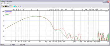
just a rough simulation to get tendencies ...
red curve is your last proposal (works good)
green curve is my modification (see pic)
Please Note:
- edge works with idealized drivers, only the pure baffle
behaviour is calculated ! (for a driver with Qts=1) the curve
may fit approximately above fs of driver.
- the "mirror" is the technique i personally use to
take into account floor reflections.
I think both configurations work, my mod is a little more
compact and asymetric, which results in a litte advantage
in rolloff behaviour in the XO range ... bass is about the same.
Have fun
Attachments
Last edited:
No. Best way to avoid deviation in directivity is to have the both
sources which shall be XOed small compared to wavelength each in itself.
Or at least to have them both in about the same relation to wavelength.
You cannot avoid the bass source to be larger than the midranger,
but cou can keep it as compact as possible.
The bass source in the "circular" approach is not small against
wavelength: It is larger than lambda/2 in both height and width while
the midranger is smaller than lambda/4. That is a big difference in
relation to wavelength.
Addditionally the distance of the drivers to be crossed over has to
be as small as possible compared to wavelength.Hi Oliver, I understand this matter: I have to consider the entire area of my 8 drivers i.e. the diameter/area of the entire footprint, including the dead spaces inbetween each of them, not only 8 x Sd...OK, OK...But are you absolutely sure I have to regard this way EVEN if the drivers are circularly surrounding the mid-driver? Because at the end, it's no less than a sort of co-axial building...
Oliver, thanks for your simulation! However I don't understand the first pic, I understand it's a mirror configuration because of the 16 drivers but where in the virtual separation line? at point "1"? so point "1" is the bottom of the baffle? also, is the black point left the mid driver place?
Thanks!
Thanks!
OK how i see it the coaxial approach truly has
its benefits.
When XOing 2 drivers (just for imagination) of equal area
the radiation would narrow in the overlap region assuming
drivers are in phase and mounted separetely.
A coaxial approach (HF disc in the middle, LF ring)
can circumvent this to a certain degree.
Also the coaxial aproach behaves symmetric for off axis
angles vertically as well as horizontally.
Also the virtual sound source stays in one point.
These are the benefits. But when looking at a 2 Way coaxial
driver say 20cm Bass with 2cm tweeter XO at 2Khz there will
be still a discontinuity in directivity. The bass driver beams below
2Khz and the tweeter will have approx evenly distribution in the
front halfroom above 2Khz.
The slope of the crossover will decide how sharp the step in
directivity will be, but it is still there no matter if coaxial
or mounted separately.
In the "woofer frame" approach above i would rate the benefit lesser
than the disadvantages because of the total growth of the bass
source, making the discountinuity problem worse.
That is my personal opinion.
The coaxial benefits (symmetry, virtual point source) are one thing.
Discontinuity in directivity of a multiway speaker is another.
The latter cannot be healed by going coaxial.
It can only be healed by matching directivity of the drivers
at crossover frequency.
When distance between drivers can be kept small compared
to wavelength and the HF driver is much smaller than the LF
driver, there is little advantage in coaxial.
Additionally the directional hearing is not very precise at low
frequencies, making the "virtual point source" benefit even lesser
at LF.
A different speaker builder will truly have a different opinion
on that matter. That is why we have a forum ...
Kind Regards
Maybe i forgot the simplest argument:
If you were on the way to make a "truly orthodox coaxial virtual point source"
it would be far more important to use a coaxial midrange/tweeter or
fullrange unit.
But you don't use such a unit although distance of midrange and tweeter
is presumably not small compared to wavelength at crossover ... and
the ear is more skilled in directional hearing at high freqencies.
Concerning orthodox coaxial speakers:
Cabasse loudspeakers Range Artis La Sphère
http://www.audio-creativ.de/Tannoy glenair 10-1.JPG
The tannoy approach is interesting in so far, as it tries to match
dispersion (using a HF tractrix horn) at crossover AND uses coaxial
configuration.
Kind Regards
Last edited:
Oliver, thanks for your simulation! However I don't understand the first pic, I understand it's a mirror configuration because of the 16 drivers but where in the virtual separation line? at point "1"? so point "1" is the bottom of the baffle? also, is the black point left the mid driver place?
Thanks!
The mirror line is at x=1m yes. I mirror horizontally because the
configuration fits better on the screen that way. There is no effect
in the result whether you mirror vertically or horizonztally.
The small point is the virtual microphone at 1.5 m distance from the baffle.
Thanks Oliver!
To say the thruth, I'm not sure about the project as I ran a few sims in Baffle Edge Diffraction Simulator and it seems the baffle could be a little small in width to get enough bass even with room boundary reinforcement...(-6db at approx 55hz, bump of +3db at 300hz vs +2 to + 3dbs from 25 to 350hz for a monopole with same woofers placement_your or mine last configs, very close to bottom)
As I want to go passive x-over this could a bit difficult to manage..What do you please think about?
The bumb can be compensated using a lower XO, that should not be a
problem. When using passive XO you will need coils with a core.
I cannot see any showstoppers.
Maybe a 6db/12db dual slope lowpass is a way to go.
What is the Qts of your woofers ?
Kind Regards
problem. When using passive XO you will need coils with a core.
I cannot see any showstoppers.
Maybe a 6db/12db dual slope lowpass is a way to go.
What is the Qts of your woofers ?
Kind Regards
Last edited:
Hi Oliver,
Yes obviously they will be cored inductors.
TangBand W5 876SD, is the driver I thought of for this project; In a BR box it is a good bass driver for the price (approx 17€). I have one pair in a speaker but I'm too lazy to open one of them and proceed to T/S parameters measurements; the manufacturer data is QTS 0.33; effective QTS through the sim (with 0.4 ohm filter and wire resistivity) is 0.348.
If you have an idea about a better driver for an OB application (single or several) with similar SD (i.e. 8x94cm²=752cm²) for approx 150€...
Cheers
3 of these could make a good job:
EUROPE AUDIO
Total Sd 1080cm² and a more OB adapted QTS (0.44), for less than 142€ per speaker !
EUROPE AUDIO
Total Sd 1080cm² and a more OB adapted QTS (0.44), for less than 142€ per speaker !
Hi crazyhub,
i personally would look for drivers with Qts >=0.6 and fs >=35 Hz.
As you have simulated, some resistance in the lowpass coils
to bring Qts on a higher value does not harm.
I am no woofer specialist, but there are some pro sound models
from eminence e.g. which seem to be widely used here for that
purpose.
Kind Regards
Oliver
- Status
- This old topic is closed. If you want to reopen this topic, contact a moderator using the "Report Post" button.
- Home
- Loudspeakers
- Subwoofers
- OB, where to place drivers?